Figure 2.8 – mx/qx hart setup sequence – Flowserve MX HART Field Unit User Manual
Page 15
15
MX/QX HART Field Unit FCD LMENIM2340-00 – 1/14
flowserve.com
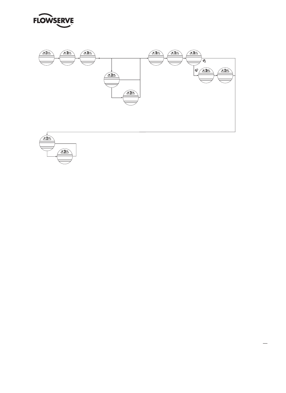
Figure 2.8 – MX/QX HART Setup Sequence
CHANGE
HART
YES
NO
(OFF)-OK?
(ENABLED)-OK?
If Hart Actuator
& Multidrop
If Hart Actuator
& not Multidrop
Address default is zero
Range is 0-63
If fail position is
“position”
If fail position is
not “position”
(OPEN)- OK?
(STOP)- OK?
(POSITION)- OK?
(CLOSE)- OK?
(STOP)- OK?
(OPEN)- OK?
(POSITION)- OK?
STATUS
(ON)-OK?
MULTI-DROP
(DISABLED)-OK?
FAIL POSITION
(CLOSED)-OK?
POLLING ADDRESS
(0)-OK?
SAVE
SETTINGS-OK?
CHANGE PROP/
DEADBAND?
PROP BAND
(5%)-OK?
DEADBAND
(2%)-OK?
MOVE TO
XXX%-OPEN
ESD ACTION
(IGNORE)-OK?
MOVE TO
XXX% OPEN
NOTE: This menu is displayed after the actuator and HART board have been powered up together at least one time.
1. Proceed through Setup to the CHANGE HART? display. Select YES to get to the STATUS display.
2. STATUS enables the user to change from the default condition to turn on and off the network control capability of
the actuator. Select NO to change the setting or YES to get to the next display. (Default = ON)
3. MULTI-DROP (ENABLED) or (DISABLED) allows the user to select the desired network topology. To change the
setting, select NO until the required option is displayed. Select YES if the setting is correct to go to the next display.
NOTE: Changing the topology also requires that the network be wired correctly for the selected topology.
NOTE: If MULTI-DROP ENABLED was chosen, skip to step 5. Otherwise, FAIL POSITION display is shown. In multi-drop
mode the input is digital only (write PV over network), so there is no analog fail action.
4. FAIL POSITION allows the user to configure the action desired upon loss of the analog input signal. The selections
are CLOSE, OPEN, STOP and POSITION. Select the desired setting and proceed to the next display.
NOTE: If POSITION is chosen as the action, a MOVE TO display will be shown where the user can select the desired
position between 0 and 100% open, in one percent increments, by selecting NO until the desired position is selected.
Select YES once the setting is correct to go to the next display.
5. POLLING ADDRESS allows the user to set the HART polling address of the unit. Point-to-Point units are typically
set to address 0, and Multi-drop units are typically set from 1-63. HART 5 masters will always set Point-to-Point
units to address 0.
6. SAVE SETTINGS allows the user to save the settings and make them active. This can result in a change in the
hardware configuration on the HART board to support the change in configuration. Select NO to return to STATUS
(step 2) and change settings. Select YES to save the HART configuration settings and go to additional network
settings.
NOTE: The configuration set in steps 1-6 will not be saved if the user does not select YES for SAVE SETTINGS.