Flowserve MX HART Field Unit User Manual
Page 59
59
MX/QX HART Field Unit FCD LMENIM2340-00 – 1/14
flowserve.com
3
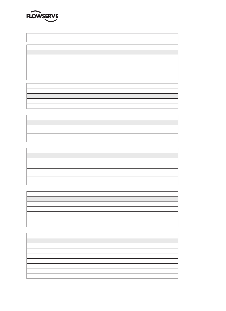
Lock All – No changes in the device’s configuration, by any master, are allowed. In addition, Device Reset or
Power Loss does not affect the lock. Any Master can unlock.
Lock Status
Bit Mask
Lock Device Description
0x01
Device Locked. Must be set if any lock is asserted in the Field Device.
0x02
Lock is Permanent. Must be set if lock does not clear on Device Reset or Power Loss.
0x04
Locked by Primary Master (Reset if Secondary Master). Must be set if locked by the Primary Master or Gateway.
0x08
Configuration Locked and cannot be changed by any application. Must be set if “Lock All” code is received.
0x10
Locked by Gateway. Must be set (along with “Locked by Primary Master”) if locked by Gateway.
Device Variable Command Code
These codes indicate whether the Device Variable’s engineering value is forced to a fixed value or is in normal operation.
Code
Transfer Function
0
Normal
1
Fixed
RTC Flags
Flag
Description
0x01
Non-Volatile Clock. When set the device contains a battery-backed clock. In this case the clock does not need
to be reset if there is a power loss.
0x02
Clock Uninitialized. The real-time clock has never been set with the date and time. For example, the clock is
volatile and power was removed from and restored to the device.
Trend Control Code
Code
Description
0
Disable
1
Enable Single Data Point Trending
2
Enable Filtered Trending – The sample is filtered using a time constant equal to one-third the trend sample
period.
3
Enable Average Trending – The value is obtained by dividing the sum of all samples in the period by the total
number of samples.
Burst Message Trigger Mode Selection Code
Code
Description
0
Continuous – The burst message is published continuously at (worst case) the minimum update period.
1
Window – The burst message is triggered when the source value deviates more than the specified trigger value.
2
Rising – The burst message is triggered when source value rises above the specified trigger value.
3
Falling – The burst message is triggered when the source value falls below the specified trigger value.
4
On-Change – The burst message is triggered when any value in the message changes.
Burst Mode Control Code
Code
Description
0
Off
1
Enable Burst on Token-Passing Data Link Layer Only
2
Enable Burst on TDMA Data-Link Layer Only
3
Enable Burst on TDMA and Token-Passing Data Link Layers
250
Reserved
251
Reserved
252
Reserved