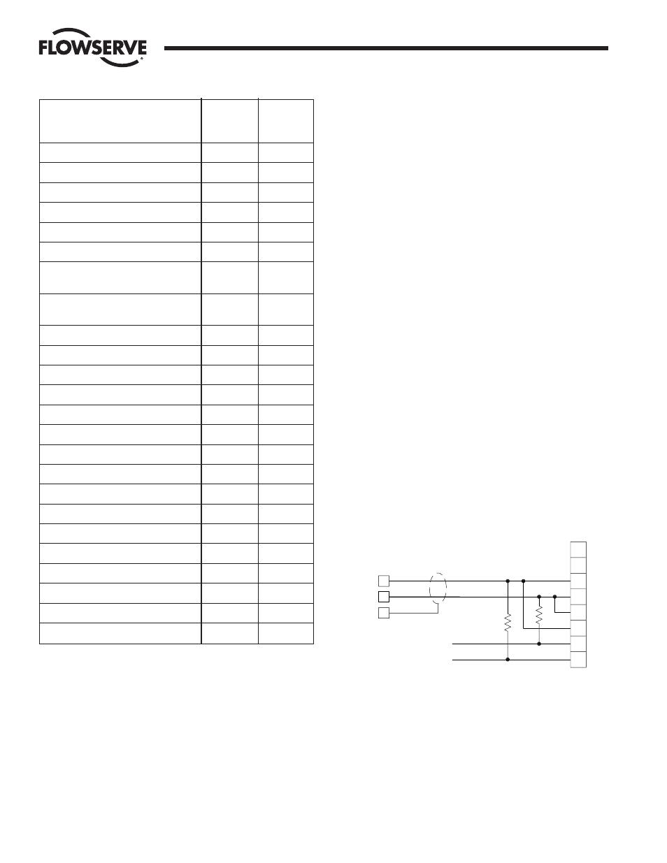
Sample rs-485 connection, Worcester controls – Flowserve Worcester Controls Electri-SAFE DataFlo User Manual
Page 14
14
Electri-SAFE DataFlo Digital Electronic Positioner
FCD WCAIM2048-01
Flow Control
Worcester Controls
4.8 Default Values (factory installed)
When default parameters are loaded in Program Mode, they are
set as follows: See paragraph 4.4.17 for the procedure to set
default values.
To restore all the parameters to the factory default settings as listed
here, advance to the PrSt parameter, momentarily press the SEL
switch, and then momentarily press the UP switch. The display will
show yES for several seconds and then again begin flashing
between PrSt and no. The factory defaults are now installed.
4.9 RS-485 Communications
NOTE: The positioner must be in the RUN MODE for communication
between the positioner and computer.
The Digital Positioner Board may be connected to a computer or
PLC via an RS-485 two-wire serial bus. Unless the computer has
an RS-485 port built in, it will be necessary to use an RS-232 to
RS-485 converter on one of the computers serial ports. If there is
more than one positioner on the serial bus, all positioner boards
except for the last one on the bus must have the 120 ohm
terminator resistor removed (see figure 1 in appendix for resistor
location). The terminator resistor is in socket pins. The
positioners should be connected to the RS-485 bus in a daisy
chain fashion. CAUTION: Do not connect two units with the same
address to the same RS-485 bus.
4.9.1 See the Worcester/McCANNA Packet Communications
specification for the communications protocol information. It
is on the software floppy diskette in the form of a txt file in
the commspec directory and is called commspec.txt.
4.9.2 The RS-485 Converter must be connected directly to
terminal strip TB1 of positioner board: terminals (1) positive;
(2) negative and the shield connected to terminal (3).
4.9.3 A floppy disk is provided with the software that is to be
installed on a computer which will allow communication with
the positioner. There is one executable program on the floppy,
ICP1.EXE, as well as several support files. The program may
be run from the floppy. Flowserve strongly recommends that
one or two backups be made of the software diskette before
using it. Write protect the disks, or copy the software to the
computer’s hard drive (create an ICP directory and then copy
all the files to that directory).
4.9.4 Setting Up The Communication Serial Port
NOTE: THE POSITIONER HAS BEEN FACTORY-SET AT A BAUD
RATE OF 38,400 bps.
The baud rate range is 1,200 bps to 38,400 bps. The baud
rate can be reset by reprogramming the positioner using the
manual keys on the positioner board (see Part 4.5) but then
will require resetting the baud rate in the communication
software. (Baud rate as shown on the positioner board display
must be the same as set up in the communication software.)
Parameter
Name
Factory
Parameter
Display
Default
Security code
CodE
unaffected
Communications address
Addr
unaffected
Optional current output module range
Ocur
4-20 mA
Setpoint direction
Sdir
RISE
Split range start point
SPrS
0.0 %
Split range end point
SPrE
100.0 %
Ramp open (CCW) time
OPEn
0 sec
(ASAP)
Ramp close (CW) time
CLOS
0 sec
(ASAP)
Setpoint function
SFc
LINEAR
Positioning deadband
dEbA
0.5 %
Loss of setpoint signal position
SPOS
0.0 %
Loss of setpoint dwell time
SPt
0 sec
Power-on position
PPOS
0.0 %
Power-on position dwell time
PPt
0 sec
Positioner lower rotational limit
yA
0.0 %
Positioner upper rotational limit
yE
100.0 %
Tight valve shut off operation
yCLS
NO
Full open valve operation
yOPn
NO
Communications rate
bAUd
38400
Valve total travel time
CyS
Unaffected
Total number of valve cycles
CyCn
Unaffected
Deviation alarm time
AdE
Unaffected
Valve high (CCW) position alarm.
AHi
100.0 %
Valve low (CW) position alarm.
ALo
0.0 %
ICS
Model 485F9 (9pin)
or 485F (25 pin)
485 Converter
1.5K
1.5K
PWR SUPPLY +9VDC
PWR SUPPLY GND
TB1
TB1
2
1
Receive -
Receive +
(SHIELD)
(NO CONNECTION)
EN\
GND
TX
TX\
RX\
RX
GND
VDC
TB1
3
Sample RS-485
Connection
Positioner Board