Worcester controls – Flowserve Worcester Controls Electri-SAFE DataFlo User Manual
Page 21
FCD WCAIM2048-01
Electri-SAFE DataFlo Digital Electronic Positioner
21
Flow Control
Worcester Controls
On the back side of the power supply (opposite LEDs) is a five-
pin connector that wires to the positioner board (see Figure 3
in the appendix). The pins are numbered 1 through 5 from left
to right. Apply 120 VAC power to the actuator. With a digital
voltmeter, pin 1 is positive and pin 2 is negative, check to see
that 5 volts DC (±10%) is available at these pins. Be careful not
to short meter leads to the positioner housing. If no DC voltage
is measured, replace power supply per paragraph 7.2.3.
7.2.3 Power Supply Replacement
(Troubleshooting chart steps 6 and 13)
a) Remove AC Power from the actuator.
b) Unplug five-pin connector from back of the power supply
housing.
c) Disconnect the white, brown, red and black wires from
terminals 1, 2, 7 and 8 coming from the power supply.
d) Remove three mounting screws and remove power
supply housing.
e) Install and wire new power supply as per d, c, b above.
f)
Apply 120 VAC power and check for 5 VDC voltage as per
paragraph 7.2.2.
7.3 Positioner Board
7.3.1 Positioner Board Replacement
(Troubleshooting chart steps 5 and 10)
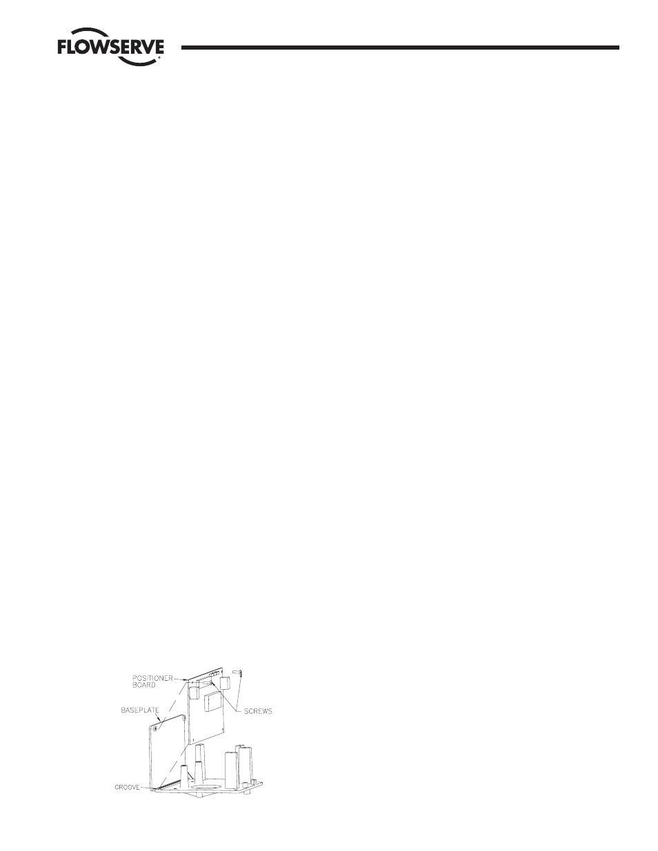
Refer to figure below.
a) Remove AC power.
b) Unplug 5-pin connector from back of power supply
housing. Disconnect the white/brown, white/violet,
orange, blue, yellow, red and black wires from board to
terminal strip points 9, 10, A, B, C, D, and E respectively.
Disconnect the potentiometer wires from terminal strip
TB2 on board. Disconnect RS-485 wires (if any) from
terminal strip TB1 on board.
c) Remove the two #4 screws and lift out the circuit board.
NOTE: It may be preferable to wire the new circuit board
to the terminal strip before mounting the circuit board to
the baseplate.
d) Locate the new positioner circuit board to the baseplate.
The bottom edge of the circuit board fits into a groove in
the baseplate as shown.
e) Secure the circuit board with two #4 x
1
/
4
" self-tapping
screws through the top two holes in the board.
f)
Make electrical connections per step b and refer to
Figures 4 and 5 in the appendix.
g) Calibrate new board per part 4.6.
NOTE: All wiring is to be run smoothly, neatly and away
from any rotating parts, using wire ties if necessary. Use
caution to avoid pinching the wires between the base and
cover flanges.
All wiring to terminal strips shall be inserted only to
midpoint of terminal strips.
7.4 Actuator Troubleshooting
7.4.1 General
Note: With no power applied to the actuator, it should be in
the full CW position. If not, remove the actuator from service
and return it to the factory. There are no field serviceable
components associated with the hydraulic pump/motor. The
solenoid coils can be replaced in the field per paragraphs
7.4.5 and 7.4.7.
7.4.2 Command Functions (CW & CCW) Voltage Check
(Troubleshooting chart steps 11 and 14)
This voltage test is done in conjunction with the calibration
procedure in order to determine initially if the problem resides
with the positioner or the actuator. Perform calibration
procedures 4.2.1 and 4.2.2 and at the same time connect a
voltmeter to measure the 120 VAC command signals at the
actuator terminal strip. When checking for CCW rotation
connect the voltmeter to terminals 1 and 7. When checking
for CW rotation connect the voltmeter to terminals 2 and 7.
7.4.3 Pump/Motor and Positioner Solenoid Valve Functions
(Troubleshooting chart step 12)
(Perform test in the actuator housing.)
Check For CCW Rotation: Operation of the hydraulic pump/motor.
(Both the CCW and CW tests should be performed with
jumper wires that have insulated probe tips.)
Remove the red wire marked 1 and black wire marked 2 from
terminals 1 and 2 in the actuator housing and tape these
leads separately.
Note: These wires are part of the bundle that goes to the
positioner housing and the two wires are removed from the
right side of the terminal strip.
Using a test cable, connect 120 volt leads (power off) to
actuator terminals 7 (neutral) and 8 (hot). Apply power to the
actuator and place and hold the jumper probes across
terminals 8 and 1. The actuator should rotate CCW until it is
stopped by the CCW limit switch 1 in the actuator housing. If