Worcester controls – Flowserve Worcester Controls Electri-SAFE DataFlo User Manual
Page 6
6
Electri-SAFE DataFlo Digital Electronic Positioner
FCD WCAIM2048-01
Flow Control
Worcester Controls
4.3 General Description of Digital Positioner
The Digital Positioner is used for intelligent control and operation
of the Electri-SAFE Electro-Hydraulic Actuator.
4.3.1 Valve Position Setpoint Input
The valve position setpoint input signal is derived from either
an analog input signal or from a digital RS485 serial input.
4.3.2 Valve Position Feedback
Valve position feedback to the digital positioner board is from
the 1,000 ohm potentiometer geared to the actuator shaft.
4.3.3 Key Features of The Digital Positioner
Easy push-button calibration of the positioner
Programmable set point direction
Microprocessor-based positioner
Programmable split range
High resolution
Programmable deadband as well as auto adjust
Cycle count
Programmable operating parameters
Hi, Low, and Deviation alarms
Four programmable position response curves
Loss of signal position and time delay
Local and remote positioner operation
Loss-of-power position and time delay
Electronic travel limits
ASCII text area in EEPROM (420 + bytes)
4.3.4 Operating Modes
The four modes of operation are:
CALIBRATION (see part 4.2 and part 4.6)
PROGRAM (see part 4.4)
LOCAL (see part 4.5)
RUN (This is also the default mode, see part 4.7.)
4.3.5 Data Readout
A four-digit LCD mounted on the positioner board provides
local data readout. Each LCD segment is controllable, which
allows display of some letters in addition to all digits.
Parameters will be identified by names, not numbers.
Provisions for numerical values with decimal points will
be made.
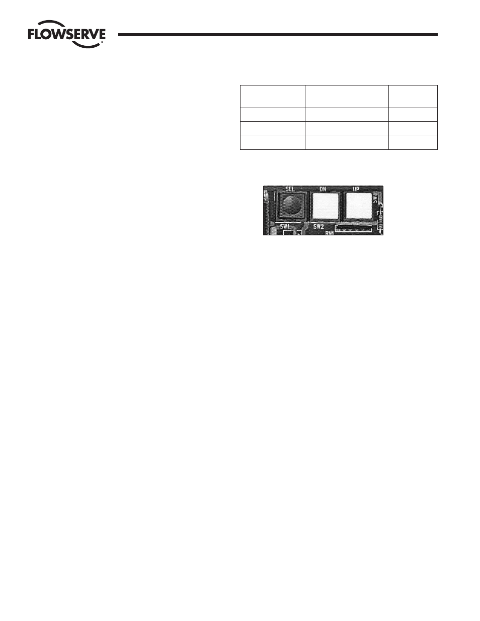
4.3.6 Local Data Entry
Three push-button switches (as shown below) on the
positioner board are used for local data entry:
SEL Selects a parameter for editing or changes modes of
operation.
UP Increases selected value or selects next parameter.
Hereafter this switch will be called UP.
DN Decreases selected value or selects previous parameter.
Hereafter this switch will be called DOWN.
In the Program Mode of operation, data is edited by pressing
the SEL switch while the parameter name is alternating with
its value. The display will then be in the Fixed Mode where
one or more digits will flash.
With a single digit flashing, pressing the UP switch will
increase the digit value by 1, wrapping from 9 to 0. Pressing
the DOWN switch will cause the next digit to blink and allow it
to be edited. Pressing the SEL switch will store the value in
non-volatile memory, discontinue editing, and return the
display to the Toggle Mode.
Note: Displayed data cannot be edited in the Run Mode.
Pressing the SEL switch in that mode causes the display to
stop alternating and only the parameter value is displayed.
4.3.7 Display Modes
The display has two modes of operation: Toggle Mode and
Fixed Mode.
In Toggle Mode (default), the display will alternate between a
parameter name and its value. In Fixed Mode (press SEL
switch), only the value appears on the display. If a parameter
is being edited, one or more digits are blinking as the value of
the parameter is being displayed.
Key combination
New mode
while in run mode
New mode
entry display
SEL
Program Mode
Prog
SEL + UP
Manual Setpoint Mode
Loc
SEL + DN
Calibration Mode
CAL