Worcester actuation systems – Flowserve DFP17 User Manual
Page 18
18
DataFlo Digital Electronic Positioner DFP17 Installation, Operation and Maintenance Instructions
WCAIM2037
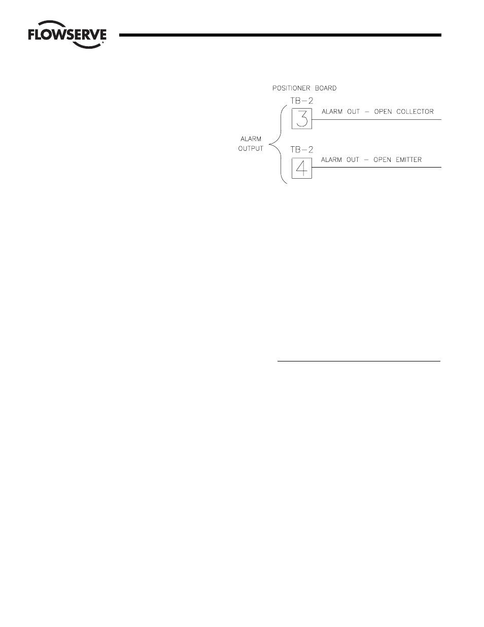
NOTE: For wiring of alarm outputs refer to diagram on
the right.
Two alarm parameters will be programmable:
Ahi:
0.0 to 100.0% For the upper rotation alarm.
Alo:
0.0 to 100.0% For the lower rotation alarm.
Load Specifications for Alarm Output:
Maximum Collector/Emitter Voltage is 50 volts DC,
maximum Collector/Emitter Current is 100 mA.
The AdE value is also shown with the programmable
parameters to show the deviation alarm time. This value
cannot be edited.
The thEr display indicate a thermal warning condition for
the DC motor driver IC.
4.4 Local Mode
Local Mode is provided to allow manual control of the positioner.
Local Mode is entered from the Run Mode by holding down the
SEL and UP switches simultaneously for three seconds. From
the Local Mode, pressing and holding the SEL switch for two
seconds will return to the Run Mode.
In the Local Mode, the display will show POS alternating with the
position. Pressing the SEL switch will stop the alternating.
Press either the UP switch to travel CCW or the DOWN switch to
travel CW. When either switch has been pressed and let up, the
brake will be applied for the programmed brake time.
4.5 Feedback Calibration Routine and Cycle Time Measurement
4.5.1 For Microchip U5 (AC board) or U3 (DC board)
Rev. V2.12 and newer only
The Calibration Mode provides a way to properly calibrate
signals used by the positioner. Periodic calibration is
recommended to maintain accurate positioning. This
mode is entered from the Run Mode by simultaneously
holding down the SEL and DOWN switches for three
seconds. From the Calibration Mode, pressing and
holding the SEL switch for two seconds will return to the
Run Mode.
When first entering the Calibration Mode, CAL, will be
displayed for two seconds and the security code will be
checked. If the required security code is not zero
(“0000”) the display will begin alternating between CodE
and 0000. Enter the security code as described earlier in
section 4.3.1.A and per section 4.2.6. If the required
security code is zero, it will not need to be entered by the
user (i.e., it will be bypassed).
After any required security code is correctly entered, a
menu allows the user to select individual calibration
procedures they wish to perform.
The user is presented with the first of several calibration
parameters. Calibration is performed in a manner similar
to parameter editing in the Program Mode. A parameter
is shown alternating with its current value. Pressing the
DOWN switch will select the next calibration parameter.
To perform the calibration procedure for a displayed
parameter, simultaneously press the SEL and UP
switches. When calibration of the selected item is
completed, press the SEL switch to return to the menu.
Also refer to section 4.1.1 for step by step procedures.
In the table below, calibration names are shown as they
appear on the display with their definition. The table also
shows the order of the procedures.
Parameter
Name
Description
SEtL
Setpoint range lower limit signal value.
SEtU
Setpoint range upper limit signal value.
PoC
Shaft position feedback value in clockwise
position.
PoCC
Shaft position feedback value in counter-
clockwise position.
Cyt
Cycle time measurement.
A. Input (setpoint) Signal Calibration
1. Use the DOWN switch to go to SEtL.
2. The display will alternate between SEtL and the
voltage resulting from the input current signal.
3. To edit, simultaneously Press and release SEL and
UP switches then: Adjust the signal source to
produce the lower input reading, e.g., a 4 mA
signal. The voltage reading should be less than
1.0 volts. Press the SEL switch to lock in the full
CW reading. Control returns to the Calibration
Menu.
4. Use the DOWN switch to go to SEtU.
Flow Control
Worcester Actuation Systems