Flowserve DFP17 User Manual
Page 27
Advertising
WCAIM2037
DataFlo Digital Electronic Positioner DFP17 Installation, Operation and Maintenance Instructions
27
6.0 APPLICATION NOTES
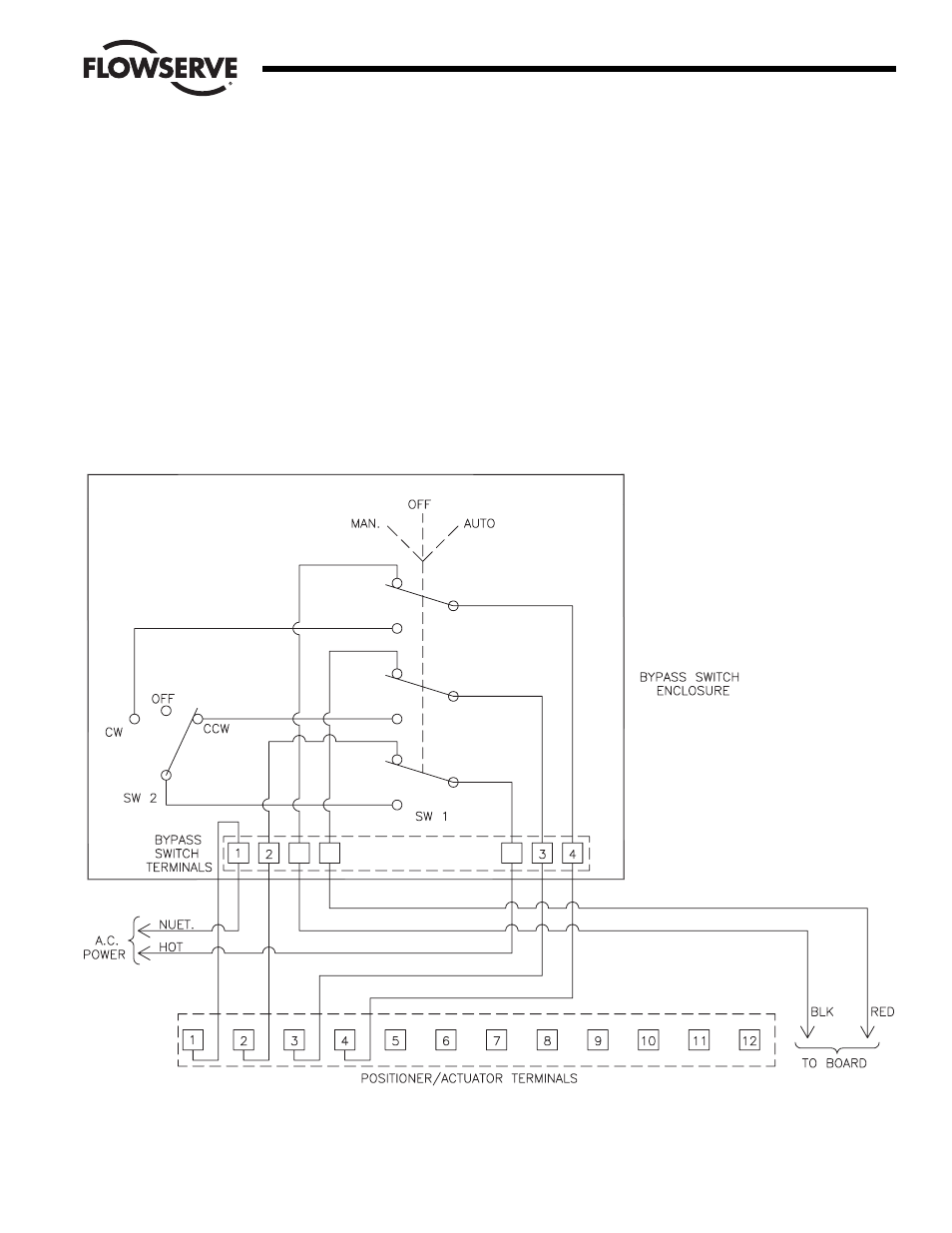
6.1 Bypass Switch for Manual Control (For 120 VAC Only)
This application is offered as a nonstandard option through
Flowserve’s Custom Products Department or may be altered by
end user. Figure 10 shows a schematic diagram of two switches
for controlling the following functions:
• One triple-pole, double-throw (TPDT) switch with center-off,
switching from automatic to manual operation.
• One single-pole, double-throw (SPDT) switch with center-off
position for manually controlling clockwise (CW), counter-
clockwise (CCW) directions of actuator.
Figure 10
Flow Control
Worcester Actuation Systems
Advertising
See also other documents in the category Flowserve Hardware:
- Tandem Seal (8 pages)
- 978 Chemiepac (12 pages)
- ISC2 Single Pusher Repair (8 pages)
- LS-300 Series Durametallic (4 pages)
- Pac-Seal Type 16 (8 pages)
- U Series BW Seals (4 pages)
- ISC2 Dual Pusher Repair (12 pages)
- ISC2 Single metal bellows seal (8 pages)
- Durametallic Double CRO (8 pages)
- VRA-C Series Durametallic (4 pages)
- ISC2 Dual metal bellows sea (12 pages)
- Single Inside Pusher Type Seal (8 pages)
- Bearing Gard (2 pages)
- X-200 (12 pages)
- GTS Series (12 pages)
- MSS Series (12 pages)
- SLC Series Interseal (12 pages)
- QB Series BW Seals (8 pages)
- SLM-6100 (12 pages)
- SLM-6200 (12 pages)
- High Temperature Metal Bellows Seals (8 pages)
- X Series BW Seals (8 pages)
- ML-200 Series Durametallic (8 pages)
- ML-200 Series Durametallic (8 pages)
- Circulator (12 pages)
- ISC Series (16 pages)
- Gas Barrier Control System (4 pages)
- CPM Series (8 pages)
- CPM Series (12 pages)
- Mechanical Seal and Seal Support System Storage (4 pages)
- RIS Seal (12 pages)
- 682 Seal Cooler (8 pages)
- ISC2 Series (8 pages)
- ISC2 Series (116 pages)
- Pac-Seal Type 52 (8 pages)
- Pac-Seal Type 31 (8 pages)
- ST Series (8 pages)
- Mechanical Seal General (16 pages)
- Dual Pressurized Seals (8 pages)
- Uniseal Series BW Seals (8 pages)
- XLC Series (8 pages)
- PSS II Durametallic (8 pages)
- PSS II (16 pages)
- ISC1SX (8 pages)
- ISC1PX (8 pages)