Fluke Biomedical 945A User Manual
Page 26
The detector cable integrity check is a pulse that is injected on the detector high voltage. The chamber
capacitance couples the pulse into the electrometer where it is seen as a high current. If either the high
voltage lead or signal lead are not connected to the chamber, the pulse does not appear on the
electrometer. The measurement cycle is interrupted for approximately one (1) second whenever the
integrity check is performed. The integrity check and high voltage check are not performed when the
instrument is reading on the three highest decades. A reading in these ranges serves as an indication of
the functioning of the instrument. The Maintenance mode operation also inhibits these checks from being
made.
There is a hysteresis built into the range changing function of the electrometer. The range change-up
occurs at the decade points whereas the range change-down occurs at 80% of the decade points. This
hysteresis results in the display of only two significant digits when in the upper 20% of a decade.
Whether or not this occurs depends on which direction the radiation level is trending. An increasing trend
will result in three significant digits while a decreasing trend will result in two significant digits.
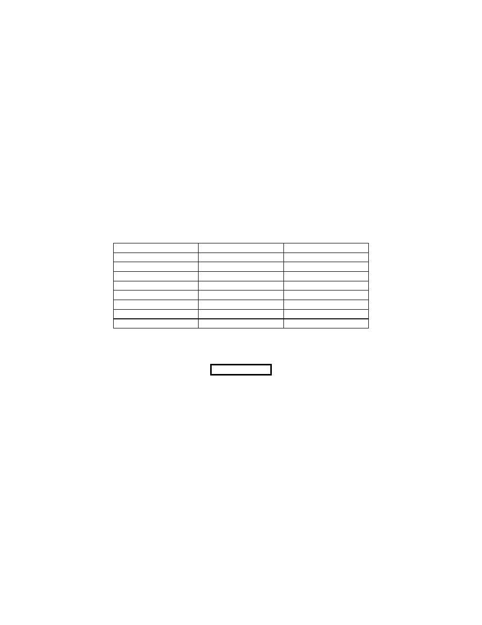
The response times for a change in reading within the same decade are listed in Table 4-1. If a change
of 100 to 1000 times the current reading occurs, the instrument will range change within a single 50
millisecond clock cycle.
Table 4-1. Response Time
DECADE RANGE RESPONSE
TIME
1
0.1 to 1.0 mR/h
80 sec.
2
1.0 to 10 mR/h
32 sec.
3
10 to 100 mR/h
16 sec.
4
100 to 1000 mR/h
4 sec.
5
1.0 to 10 R/h
2 sec.
6
10 to 100 R/h
0.9 sec.
7
100 to 1000 R/h
0.2 sec.
8
1.0 k to 10 kR/h
0.2 sec.
A manual electronic check source may also be initiated from the UDR by the operator to check detector
operation. Upon removing the check source request, the UDR again displays the detector output
CAUTION
Do not actuate the check source when the reading is above 1 R/h.
The radiation measurement is additive to the check source signal
resulting in improper values from the check source. This may
result in the UDR indicating a failure when the instrument is
operating correctly.
The detector preamplifier contains a High Voltage/Communications Interface Board containing an RS232
driver, a Victoreen Communications Interface Driver, the detector high voltage power supply, a local 0 -
10 Vdc analog output, and a -12 Vdc open collector alarm output.
4-2