Fronius Power Control Card User Manual
Page 45
43
EN
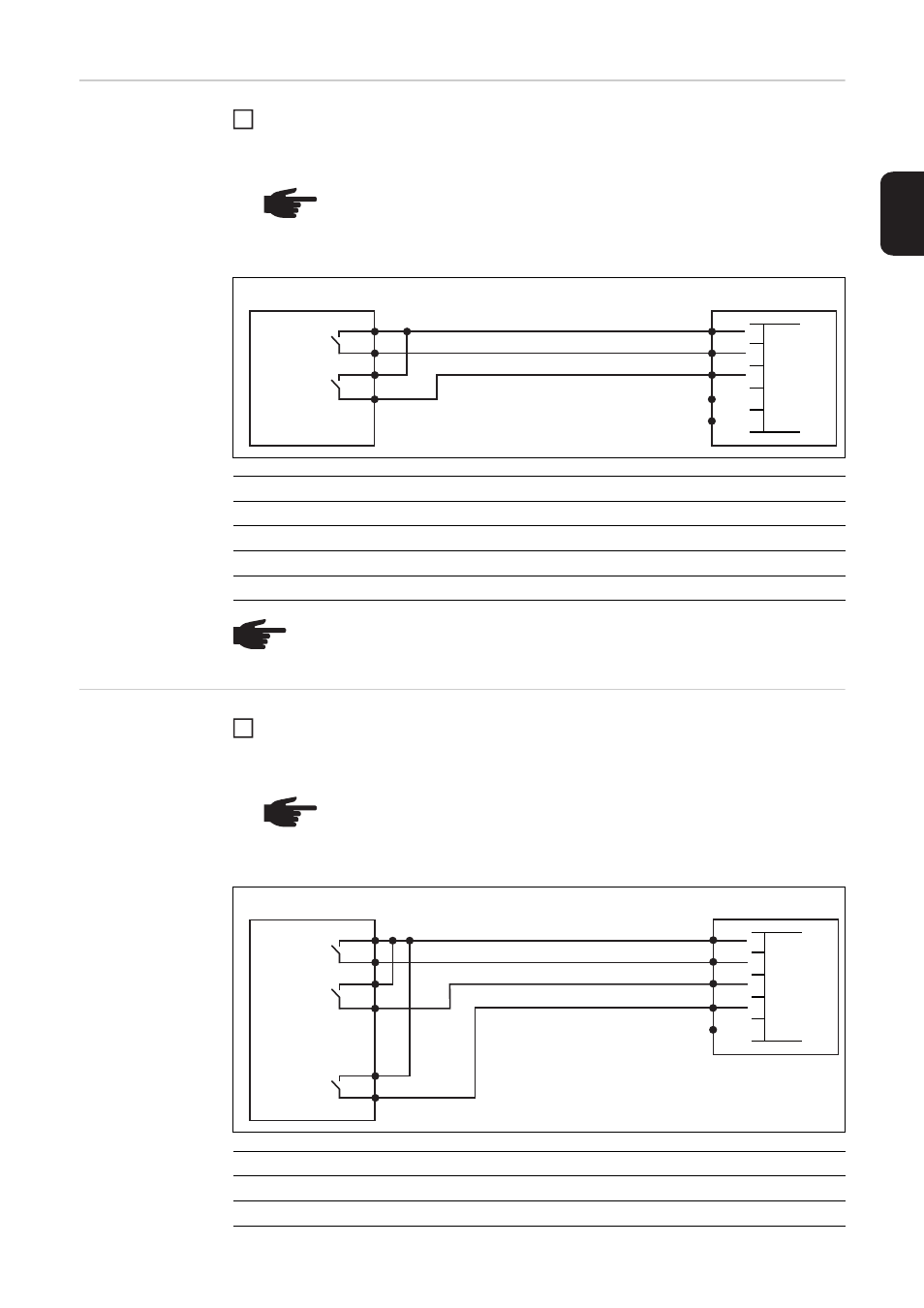
Connecting the
Fronius Power
Control Card to a
2-relay ripple con-
trol signal receiv-
er
Connect the ripple control signal receiver and Fronius Power Control Card plug using
a 3-pin cable, as shown in the connection diagram below
Tightening torque for the terminals: 0.25 Nm
Connecting the
Fronius Power
Control Card to a
3-relay ripple con-
trol signal receiv-
er
Connect the ripple control signal receiver and Fronius Power Control Card plug using
a 4-pin cable, as shown in the connection diagram below
Tightening torque for the terminals: 0.25 Nm
NOTE! The terminals on the plug for the ripple control signal receiver are de-
signed to accommodate a maximum cable cross-section of 1.5 mm².
A screened cable is recommended if the distance between the Fronius Pow-
er Control Card and the ripple control signal receiver is greater than 10 m.
Ripple control signal receiver
Fronius Power Control Card
Power
Relay 1
Relay 2
100%
open
open
60%
closed
open
30%
open
closed
0%
closed
closed
NOTE! Cables are not monitored in 2-relay operation. Cable breaks are not de-
tected and displayed as faults.
1
1
2
1
2
34
5
GND
D1
D2
D3
D4
NOTE! The terminals on the plug for the ripple control signal receiver are de-
signed to accommodate a maximum cable cross-section of 1.5 mm².
A screened cable is recommended if the distance between the Fronius Pow-
er Control Card and the ripple control signal receiver is greater than 10 m.
Ripple control signal receiver
Fronius Power Control Card
Power
Relay 1
Relay 2
Relay 3
100%
open
open
open
60%
closed
open
open
1
60 %
30 %
0 %
1
2
3
1
2
34
5
GND
D1
D2
D3
D4