FSR SPC-20 User Manual
Page 3
POWER PRODUCT GROUP
Phone: 973-785-4347 Fax: 973-785-3318 Web: www.fsrinc.com E-Mail: [email protected]
FSR
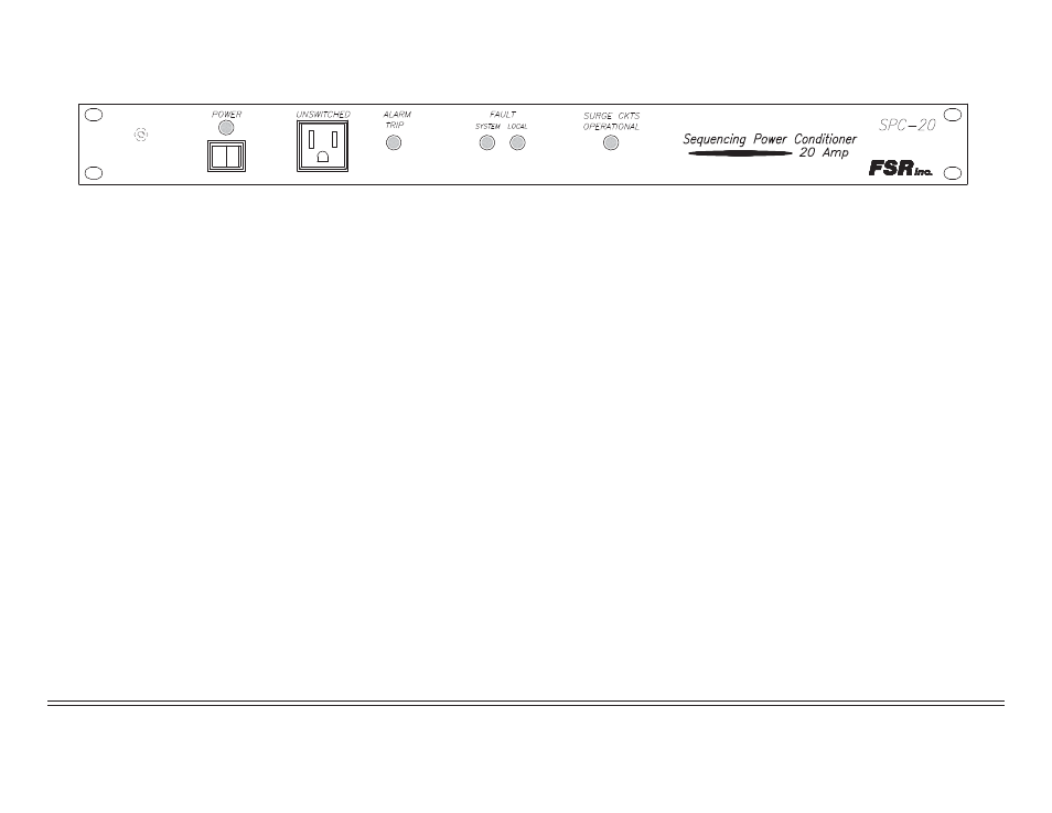
SPC-20 FRONT PANEL
SYSTEM POWER SWITCH AND LED: when the system LED is off, pressing the system switch will start the turn-on procedure, and the LED
will illuminate. When the system LED is on, pressing the system switch will start the turn-off procedure, and the LED will turn off. This LED blinks
on power up and power down until the cycle is complete.
UNSWITCHED OUTLET: this outlet is active at all times the equipment is plugged in.
TRIP LAMP: a ground closure on the remote trip input (rear panel remote control strip) will sequence the system down and latch on the trip lamp.
After the remote trip input is cleared, the trip lamp can be reset by pressing the momentary system power switch.
SYSTEM FAULT LAMP: this supervisory indicator will illuminate to indicate that an enabled AC circuit is not receiving AC power (faulty output
circuit), or that a disabled AC circuit continues to receive power (incorrect system wiring, shorted output circuit, etc.). A system fault indication will
be provided when a fault indication is detected in the SPC-20 or any expansion stages.
LOCAL FAULT LAMP: this supervisory indicator will illuminate to indicate that a fault has occurred at this local unit. A local fault on any unit in
the system will also activate the system fault lamp.
NOTE: System and Local Fault lamps can be illuminated if any of the three switched rear AC outlets are unloaded. All outlets should be
connected to a load for proper lamp indication.
SURGE CIRCUITS OPERATIONAL: provides supervisory indication that the surge suppression cicuitry is fully functional.