FSR SPC-20 User Manual
Page 4
POWER PRODUCT GROUP
Phone: 973-785-4347 Fax: 973-785-3318 Web: www.fsrinc.com E-Mail: [email protected]
FSR
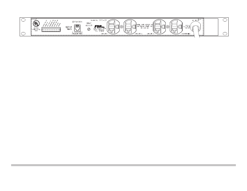
SPC-20 REAR PANEL
Rear Panel Control Functions:
NOTE: All remote control and expansion port connections are short circuit
and overload protected.
REMOTE CONTROL PORT: This pluggable screw terminal provides
for remote operation of the SPC-20 as follows:
SURGE FAULT LAMP: Provides 12 volts at 100 ma when the surge circuits are
worn out. It is in a high impedance state when off.
POWER LAMP: Provides 12 volts at 100 ma when the system is on. High impedance
when the system is off.
SYSTEM FAULT OUTPUT: This output goes high (+12V) when there is a fault on
the local or expansion units.Output rated at 100 ma.
NOTE: While each lamp output is rated at 100 ma total current draw
from all three together should not exceed 150 ma.
SYSTEM MOMENTARY SWITCH: This input may be used to remotely control
power-up/down of the system from momentary contact switch. Multiple control loca-
tions may be used by connecting switches in parallel.
SYSTEM MAINTAINED SWITCHED: This input may be used to remotely control
power-up/down of the system from a security key switch or other maintained closure
source. Only one control location may be used with a maintained switch input.
ALARM TRIP SWITCH: A closure on the remote trip input from the fi re alarm or
other emergency shutdown system will latch the trip lamp and initiate a power-down
sequence. This input will override all local and remote inputs for the duration of the
closure. To clear the trip if a momentary switch is used to power up the system, just
press the system on/off switch off and then on. A system using a maintained switch
will automatically power up once the trip input is cleared.
AUXILIARY: This output provides a ground closure when the rack circuit is enabled.
Output rated at 100 ma.
GROUND (GND): All switch inputs and lamp outputs are referenced to ground.
EXPANSION PORT: Control for expansion units. It requires a standard
6 conductor telephone type (RJ) cable wired straight
through (pin 1 to pin 1 etc.). DO NOT PLUG IN A TELEPHONE.
DELAY ADJUST: Trim control enables the user to set the initial delay
(going from circuit 1 to circuit 2 over a range of 1 to 50 seconds. All subsequent delays
will be one to three seconds, dependent on the adjustment.
NOTE: See specifi cations section for details about the timing sequence.
CIRCUIT 1 OUTLET: This half of the duplex outlet will provide 120
VAC upon activation of the system on switch.
CIRCUIT 2 OUTLET: This half of the duplex outlet will provide 120
VAC after the initial delay time.
CIRCUIT 3 OUTLET: This half of the duplex outlet will provide 120
VAC after the faster delay.
UNSWITCHED: This half of the duplex outlet is powered all the time
the unit is plugged in. Both this outlet and the one on the front have surge protection as
well as line fi ltering.
20 AMP LINE CORD: must be plugged into a true 20 amp outlet.
NOTE: THE TOTAL CURRENT, FROM ALL RECEPTACLES, THAT MAY
BE DRAWN FROM THIS UNIT IS 16 AMPS (UL REQUIREMENT).