Operation, Software configuration, Interface – GAI-Tronics 7085-005-UL, 7085-005-EX SmartSeries Multi-Party Hazardous Area Handset/Speaker Amplifier Enclosure w/ RTU Control User Manual
Page 11
Pub. 42004-697L2B
Model 7085-005-UL/EX SmartSeries Multi-Party Haz. Area Amp. Enclosure with RTU
Page
11 of 15
\\s_eng\gtcproddocs\standard ioms - current release\42004 instr. manuals\42004-697l2b.doc
11/07
Configuration 3
In the third configuration, the relay output circuit is non-
supervised. This means the RTU can command a system
device to activate or deactivate without the integrity of
the external circuit being verified. In this configuration,
both inputs are available.
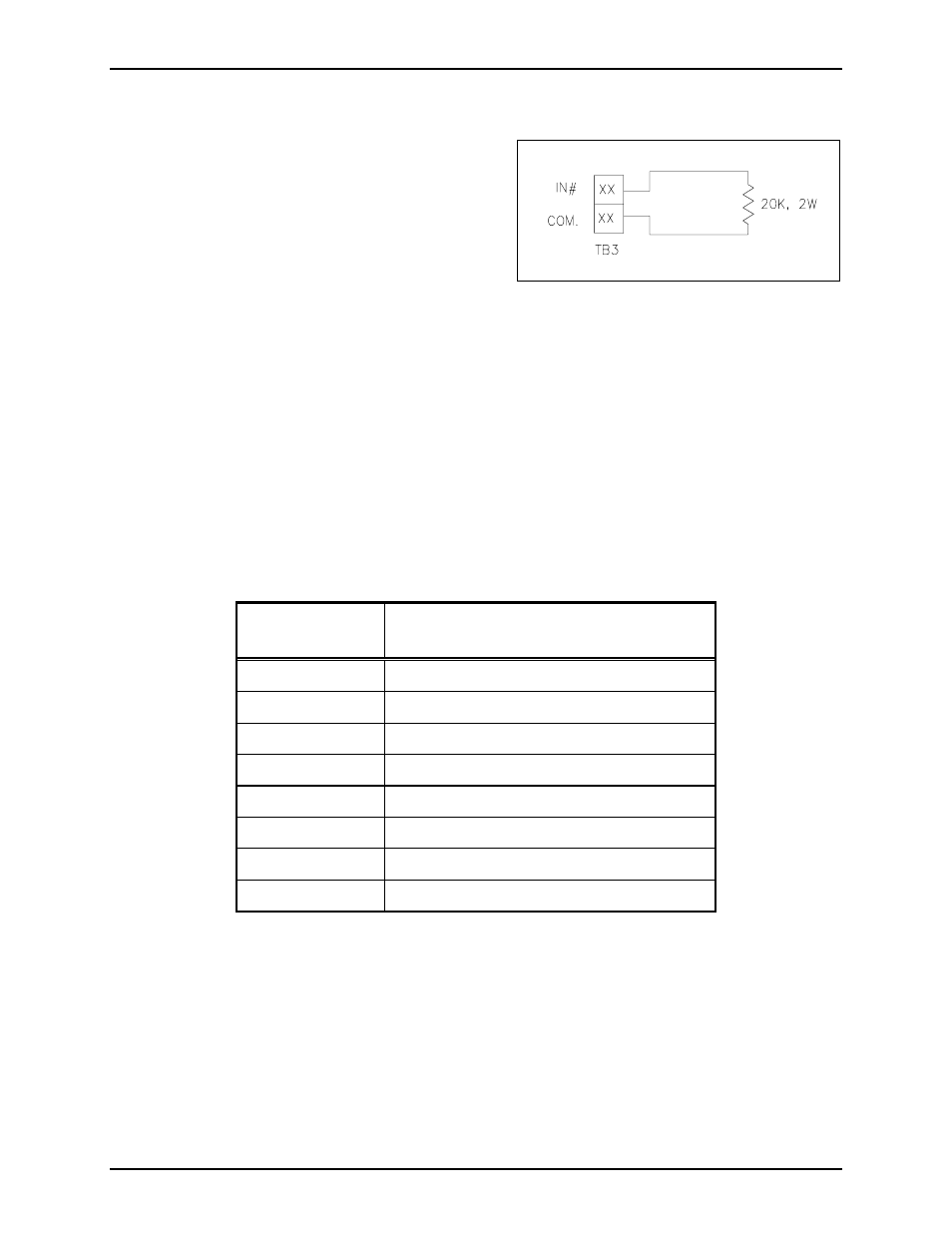
N
OTE
: Unused inputs must be terminated at terminal
block TB3 with a 20 k-ohm, 2-watt resistor. Resistors
are supplied with the units. See Figure 11.
Software Configuration
The software configuration of the RTU is accomplished through the use of the System Start-up Tool
(SST). The type of RTU is dependent on the hardware configuration. Before setting up the software, it is
important to know how the inputs and outputs will be used.
Interface
Use the ribbon connector supplied with the unit to connect the SmartSeries relay circuit to the connector at
the base of the SmartSeries station. Wiring to the RTU is performed by connecting the external circuits to
the appropriate lugs on the TB3 terminal block located on the rear panel on the enclosure. The following
table shows the wiring for TB3:
Terminal Block
Lug No.
Label
TB3-23 IN
1
TB3-24 Common
TB3-25 IN
2
TB3-26 Common
TB3-27 Spare
TB3-28
Line (hot) 120 V ac 50/60 Hz, 2.5 amps max.
TB3-29
Neutral 120 V ac 50/60 Hz
TB3-30 Earth
ground
The SmartSeries RTU is pre-wired from the factory to support one supervised input and one supervised
relay output. To disable the supervision of the relay output circuit by IN 1, disconnect the orange wire
going to the relay circuit card located at TB3-23. This is the only wiring modification necessary for any of
the three RTU configurations.
Operation
The supervised input and relay output functions are supported by the ADVANCE system. Refer to
GAI-Tronics Pub. 42004-699L2 for Model 709-901 Handset/Speaker Amplifier for detailed operational
instructions.
Figure 11. Unused Input
- 708-001-UL, 708-001-EX SmartSeries Single Party Hazardous Area Handset/Speaker Amplifier Enclosure 7085-004-UL, 7085-004-EX SmartSeries Multi-Party Hazardous Area Handset/Speaker Amplifier Enclosure w/ Alternate Page 7085-004-EX-F07049 SmartSeries Multi-Party Hazardous Area Amplifier Enclosure with Alternate Page 7085-001-UL, 7085-001-EX SmartSeries Multi-Party Hazardous Area Handset/Speaker Amplifier Enclosure 708-001-EX-F07048 SmartSeries Single Party Hazardous Area Amplifier Enclosure 7085-005-EX-F07050 SmartSeries Multi-Party Hazardous Area Amplifier Enclosure with Alternate Page