Enclosure placement, Hardware configuration – GAI-Tronics 7085-005-UL, 7085-005-EX SmartSeries Multi-Party Hazardous Area Handset/Speaker Amplifier Enclosure w/ RTU Control User Manual
Page 3
Pub. 42004-697L2B
Model 7085-005-UL/EX SmartSeries Multi-Party Haz. Area Amp. Enclosure with RTU
Page
3 of 15
\\s_eng\gtcproddocs\standard ioms - current release\42004 instr. manuals\42004-697l2b.doc
11/07
Enclosure Placement
All GAI-Tronics Page/Party
®
units are wired in parallel. Good system layout design minimizes the cable
required for each installation. GAI-Tronics multi-conductor cable, designed especially for this application,
is recommended. For the number, size, and color-coding of conductors refer to the appropriate system
connection diagrams.
System layout and power cable length are very important when installing Page/Party
®
equipment.
Although it varies for different systems, the general guideline is that the total power cable length should not
exceed one mile (5280 feet) for 120 V ac systems. The total cable length is the most important
consideration while cable length between the stations is generally not a factor.
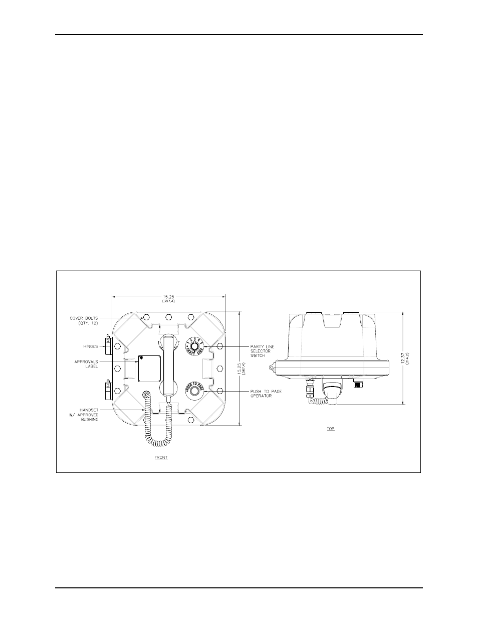
Hardware Configuration
External
The multi-party enclosures each contain a handset with an approved gland, push-to-page operator, a party
line selector switch, and applicable approval labeling. The handset rests on a cradle, which has a magnetic
reed switch located behind it to signal an off-hook condition. The enclosure itself has 12 cover mounting
bolts located around the perimeter of the enclosure, and a set of aluminum hinges located on the left side.
See Figure 2.
O utside U SA: 1-610-777-1374
In USA : 1-800-492-1212
G AI-TR O NIC S SER VIC E CEN TER S
G AI-TRO NICS C ORPORATION
P.O. BOX 1 060 READING, PA 19 607
NO US ER S ER VICE ABLE PARTS INSID E.
R EFER SER VIC ING TO Q UALIFIED PER SO NNE L ON LY.
Figure 2. Model 7085-005-UL/EX Outline Drawing
- 708-001-UL, 708-001-EX SmartSeries Single Party Hazardous Area Handset/Speaker Amplifier Enclosure 7085-004-UL, 7085-004-EX SmartSeries Multi-Party Hazardous Area Handset/Speaker Amplifier Enclosure w/ Alternate Page 7085-004-EX-F07049 SmartSeries Multi-Party Hazardous Area Amplifier Enclosure with Alternate Page 7085-001-UL, 7085-001-EX SmartSeries Multi-Party Hazardous Area Handset/Speaker Amplifier Enclosure 708-001-EX-F07048 SmartSeries Single Party Hazardous Area Amplifier Enclosure 7085-005-EX-F07050 SmartSeries Multi-Party Hazardous Area Amplifier Enclosure with Alternate Page