Installation – GAI-Tronics 7085-005-UL, 7085-005-EX SmartSeries Multi-Party Hazardous Area Handset/Speaker Amplifier Enclosure w/ RTU Control User Manual
Page 2
Pub. 42004-697L2B
Model 7085-005-UL/EX SmartSeries Multi-Party Haz. Area Amp. Enclosure with RTU
Page
2 of 15
\\s_eng\gtcproddocs\standard ioms - current release\42004 instr. manuals\42004-697l2b.doc
11/07
Installation
These enclosures must be installed by trained, qualified and
competent personnel. Installation must comply with state and
national regulations, as well as safety practices for this type of
equipment.
CAUTION
Do not install this equipment in
hazardous areas other than those indicated on the approval
listing in the Specifications section of this manual. Such
installation may cause a safety hazard and consequent injury
or property damage.
The mounting location must be flat and provide proper
clearance, rigidity and strength to support the enclosure and all
contained devices. The enclosures are equipped with factory-
installed hinges. The enclosures should be mounted with hinges
on the left.
WARNING
Do not mount the enclosure with hinges
on the top or bottom side.
Securely fasten the enclosure to the mounting location, using
1/2-inch diameter steel mounting bolts and washers, or washer
head bolts.
WARNING
Do not disconnect equipment while energized.
Insure proper grounding to protective earthing.
Inspect and clean the machined flange flame joint surfaces of both the cover and box. Surfaces must be
smooth, free of nicks, scratches, dirt or any foreign particle build-up that would prevent a proper seal.
Surfaces must seat fully against each other to provide a proper explosion-proof joint. Clean surfaces by
wiping with a clean lint-free cloth.
Apply a light coat of Killark “LUBG” lubricant to flange surfaces and close the cover. Install and tighten
all cover bolts to 30 ft.-lbs. Make certain no cover bolts are omitted. Use only those bolts supplied with
the enclosure.
When installing an add-on station, consult the appropriate system layout diagrams. These figures, when
used in conjunction with the station installation information and cable layout guide, should provide all the
information necessary to install additional Page/Party
< stations.
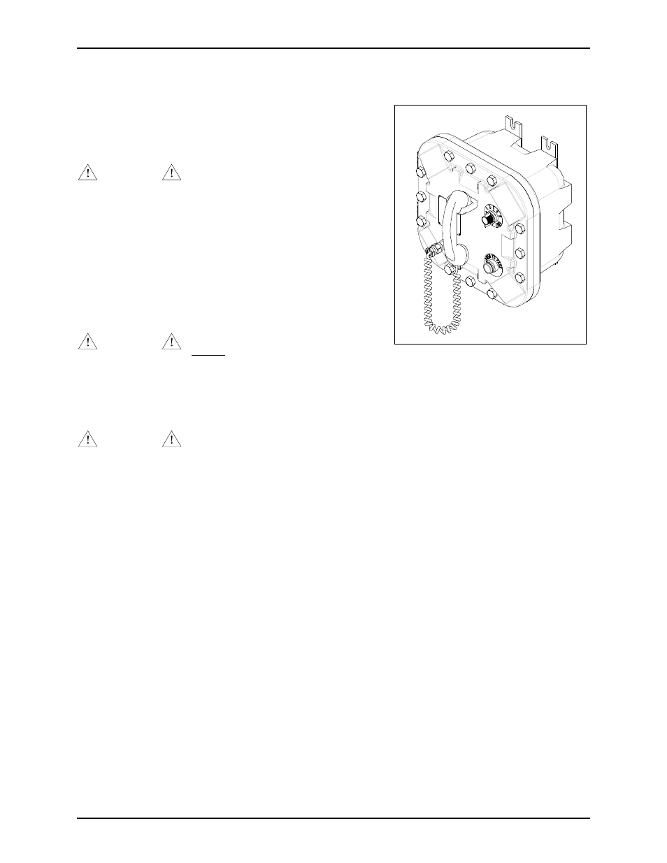
Figure 1. The Model 7085-005-UL/EX
- 708-001-UL, 708-001-EX SmartSeries Single Party Hazardous Area Handset/Speaker Amplifier Enclosure 7085-004-UL, 7085-004-EX SmartSeries Multi-Party Hazardous Area Handset/Speaker Amplifier Enclosure w/ Alternate Page 7085-004-EX-F07049 SmartSeries Multi-Party Hazardous Area Amplifier Enclosure with Alternate Page 7085-001-UL, 7085-001-EX SmartSeries Multi-Party Hazardous Area Handset/Speaker Amplifier Enclosure 708-001-EX-F07048 SmartSeries Single Party Hazardous Area Amplifier Enclosure 7085-005-EX-F07050 SmartSeries Multi-Party Hazardous Area Amplifier Enclosure with Alternate Page