GAI-Tronics 7085-005-UL, 7085-005-EX SmartSeries Multi-Party Hazardous Area Handset/Speaker Amplifier Enclosure w/ RTU Control User Manual
Page 9
Pub. 42004-697L2B
Model 7085-005-UL/EX SmartSeries Multi-Party Haz. Area Amp. Enclosure with RTU
Page
9 of 15
\\s_eng\gtcproddocs\standard ioms - current release\42004 instr. manuals\42004-697l2b.doc
11/07
RTU PCBA Configuration
The SmartSeries RTU allows three choices of operational configurations. Select the configuration that best
suits your need for circuits. The following table lists the RTU configurations:
Configuration Inputs
Outputs
1
1 supervised input
1 supervised relay output (factory setting)
2
2 supervised inputs
No relay output
3
2 supervised inputs
1 non-supervised relay output
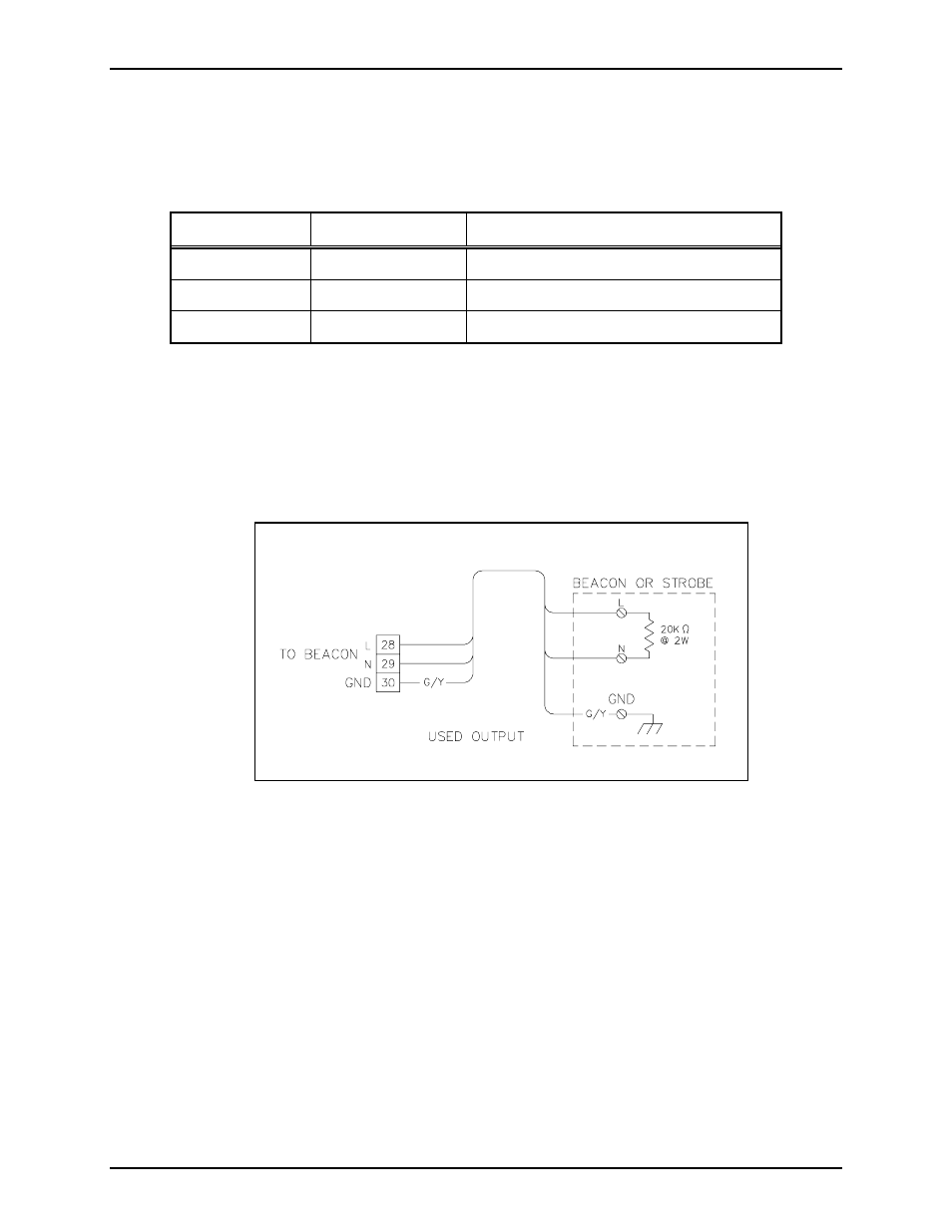
Configuration 1
In the first configuration, the relay output is supervised to continually ensure the integrity of the external
circuit. The first input, IN 1, is used to support supervision of the relay output circuit. This wiring method
requires the use of a 20 k-ohm, 2-watt resistor placed in parallel to the relay output device (e.g. a beacon or
strobe) as shown in Figure 8.
Wire the terminating resistor as close as possible to the beacon. Supervision is performed during non-
activation of the relay output using IN 1. The second input, IN 2, remains available for detecting switch
activations. The following section describes switch wiring choices. The RTU provides 120 V ac for
beacon power on pins TB3-28, TB3-29, and TB3-30.
N
OTE
: This configuration is hardwired at the factory.
Figure 8. Beacon or Strobe
- 708-001-UL, 708-001-EX SmartSeries Single Party Hazardous Area Handset/Speaker Amplifier Enclosure 7085-004-UL, 7085-004-EX SmartSeries Multi-Party Hazardous Area Handset/Speaker Amplifier Enclosure w/ Alternate Page 7085-004-EX-F07049 SmartSeries Multi-Party Hazardous Area Amplifier Enclosure with Alternate Page 7085-001-UL, 7085-001-EX SmartSeries Multi-Party Hazardous Area Handset/Speaker Amplifier Enclosure 708-001-EX-F07048 SmartSeries Single Party Hazardous Area Amplifier Enclosure 7085-005-EX-F07050 SmartSeries Multi-Party Hazardous Area Amplifier Enclosure with Alternate Page