Gasboy 9120 Pulser User Manual
Gasboy Hardware
032006 Rev. 9223
Page 1
PULSER KIT INSTRUCTIONS, 9120/7520
This instruction sheet shows how to install the 10:1/100:1 Pulser Kit for 9120/7520. Be sure to follow all warnings
and safeguards as outlined in the enclosed Warnings and Safeguards sheet before working on the unit.
Kit Contents (10:1 Pulser Kit 025929; 100:1 Pulser Kit 025930)
P/N
Description
Qty
015451 Bracket, Pulser, 9120
1
051790 Screw, ¼-20x ½ HHC
2
068891 Washer, Lock, ¼ 1114
2
021788 Pulser, 10:1 VR (025929 only)
1
047648 Pulser 100:1, VR (025930 only)
1
054827 Shaft-Drive Pulser
1
025015 Elbow, Conduit ½ x 45 M/F
1
025045 Elbow, Conduit ½ x 90 M/F
1
021372 Conduit, ½ x 4-½
1
053625 Screw, 6-32 x 3/8, Pn Hd
3
066400 ½ UNY Explosion Proof Conduit Union
1
039130 Nut, Conduit Lock
1
022050 Conduit, Pulser to Frame
1
P/N
Description
Qty
003515 Junction Box Cover
1
003340 Junction Box
1
042290 Pin, Cotter, 3/64 x ½
2
034715 Link-Drive Pulser
1
053000 Screw, 10-32 x 3/8
2
Z09273 Nut, Hex Keps #10-32
2
022431 Gear Train, Top
1
022432 Gear Train, Bottom
1
034709 Link, Computer-Drive
1
042130 Pin, Groove, 1/8 x 5/8
2
021058 Conduit Fitting, 90 M/F
1
021986 Coupling, ½ Conduit
1
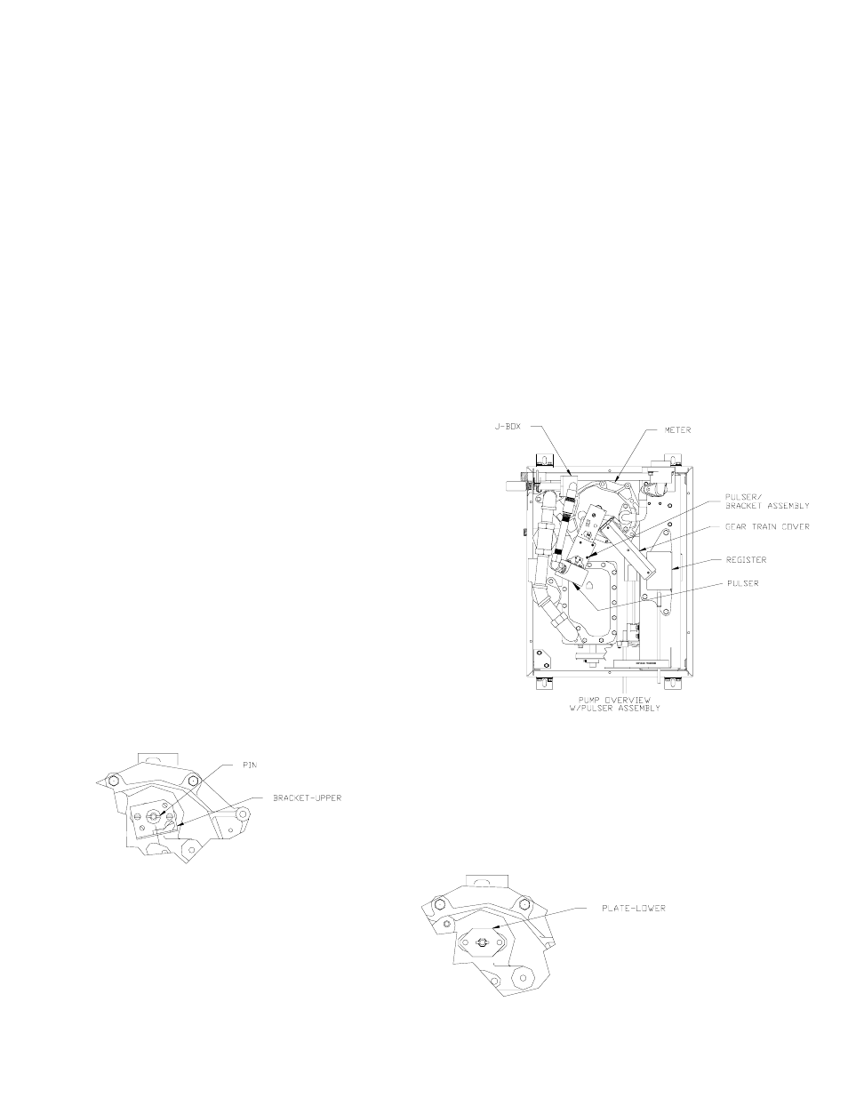
1.
Remove screw that holds gear train cover to register and set
aside.
2.
Remove screw on other end of gear train cover fastened to
bracket and set aside.
3.
Remove and set aside gear train cover.
4.
Remove brass link-drive from meter; this part will not be re-
used.
5.
Knock out pin from meter shaft and discard.
6. Remove and discard 2 screws securing bracket to meter.
Remove upper bracket; reserve for later use.
7. Remove two screws and remove retaining plate
from meter (see illustration for Steps 10-12 for
retaining plate location).