Gasboy Vapor Assist User Manual
Gasboy Hardware
032170 Rev. 8279
Page 1
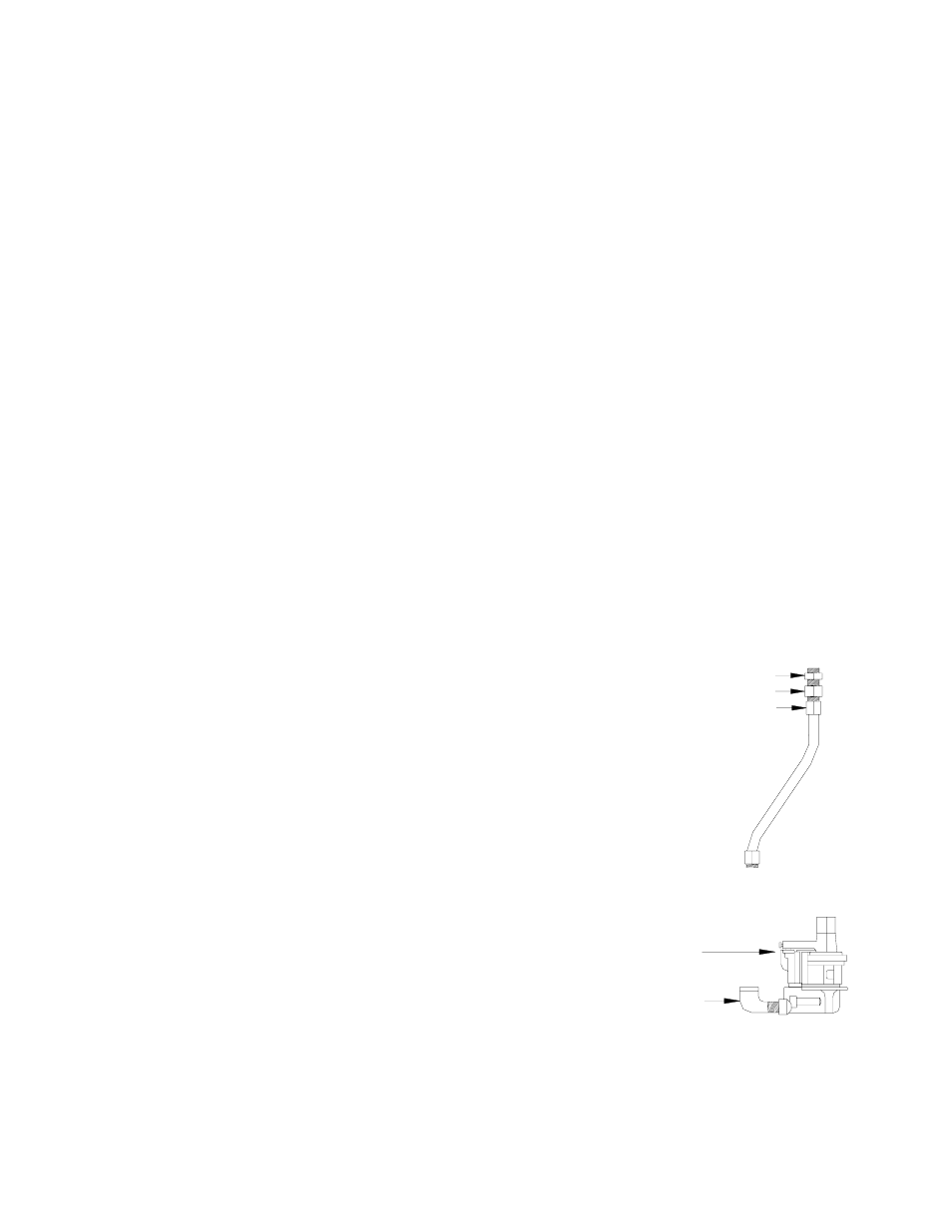
Bushing
Swivel
Jumper Hose
Pumping Unit
3/4" Elbow
VAPOR ASSIST INSTALLATION INSTRUCTIONS
For Series 8753E, 8853E, 9153A, and 9853A Single and Twin Models
This instruction sheet covers the installation of the Vapor Assist System for the models named above. Assembly
and installation of a Vapor Assist System requires a kit containing the following:
Qty.
P/N
Description
1
017270
¾” to 1” Bushing*
1
030424
¾” Hardwall UL 1’ 9” hose
1
028930
¾” Rubber Grommet
1
045802
Plate, Vapor Assist
1
047302
Pulley, 5/8” Bore, 2.6 Dia.
1
012163
Belt, A35
1
035282
Warnings and Safeguards
1
032169
Template
1
046631
Decal, Nozzle/Hose/Clamp
1
032170
Instruction Sheet
*Required for units with 1” discharge only.
Qty.
P/N
Description
1
N/A
External Vapor Pump
1
N/A
Pump Cover
1
N/A
Bellowless Nozzle
1
N/A
Breakaway
1
N/A
Hose Retractor Clamp
1
N/A
¾” Elbow, 90°
2
Optional
Thermoid Inverted Coaxial
Hose***
1
N/A
Metal Mounting Plate **
2
N/A
Locking Nuts
2
N/A
Set Screws
**Discard item and use P/N 045802 plate noted at left.
***Must be a UL-Listed Inverted Coaxial Hose assembly.
1.
Read all instructions before beginning. Installation should be done according to the instructions on this sheet.
Also, read and follow all precautions regarding remote dispensers and pumps on the Warnings and
Safeguards sheet, 035282, included in the kit. SAFETY NOTE: Before drilling or performing any other
operation which may generate a spark, we recommend removing the dispenser and other pertinent
equipment a safe distance from the island.
2.
Turn off power to the dispenser at the breaker and activate emergency shutoff valve.
3.
On models 8853E/ETW, 9153A/ATW, and 9853A/ATW, replace existing motor pulley and V-belt with supplied
pulley and V-belt. Model 8853ETW1 does not require this conversion.
Assemble Product Jumper Hose
4.
Use a UL-Classified gas- and oil-resistant pipe compound on all threads
when assembling these components. NOTE: All further references to
pipe compound in these instructions imply UL-classified pipe compound.
5. Assemble ¾”-1” bushing (017270) to ¾” jumper hose/swivel assembly
(030424).
6. Set
aside.
Assembling Pumping Unit
7.
Using pipe thread compound, attach ¾ x 90° elbow into product
connector on bottom of OPW pumping unit (Blackmer Model
VRFO, ID No. 2).
8.
Thread set screws into the pump. Use a 1/8” Allen wrench to fully
tighten. Remove the protective vapor connection plug from the
vapor connection on the OPW pumping unit. Be careful not to
allow any foreign matter, such as dirt or metal shavings to get
into the pump fitting. This could cause pump seizure and
malfunction.
9.
Gasboy recommends that you install a UL-Listed vapor line shear valve, such as OPW 60VSP as part of the
new vapor line plumbing. Refer to instructions supplied with shear valve for installation details.