Gasboy RS-485 Interface Kit User Manual
Gasboy Hardware
C35405 Rev. 8008
Page 1
INSTRUCTIONS FOR RS-485 INTERFACE KIT, C06483
Locate and identify the following parts from the RS-485 Interface Kit. Hardware and quantities may vary.
QTY
PART NO.
DESCRIPTION
1
C06389
RS-485 I/F PCB
2
C08381
Standoff, M/F 6-32 3/4"
2
068843
Washer, #6 External Tooth
2
C08759
Screw, 6-32 x 3/8
1.
Installing this kit involves DC wiring to the fuel management system. Read Sections 3 and 4 of the Pump/Dispenser
Installation Manual and your fuel management system Installation Manual before proceeding.
2.
Turn off the circuit breakers supplying power to the MICRO, LIGHTS and FEED.
3.
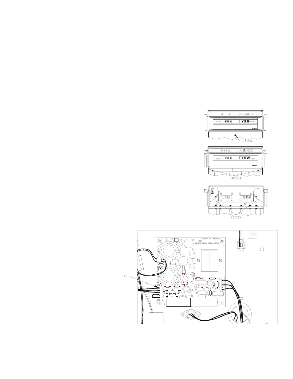
Unlock and remove the front panel.
4.
Remove the two bolts located over the tabs of the bezel assembly. Lift the bezel
assembly upwards and out to remove.
5.
Loosen, and remove if necessary, two screws located on the left and right door
support brackets and pivot the display panel down.
6.
Pull the connector off P1 (a) on the
power supply. After a few seconds,
reconnect P1.