Gasboy 120VAC Fluorescent Light Kit User Manual
Gasboy Hardware
C35404 Rev. 8120
Page 1
INSTRUCTIONS FOR
120 VAC (C06480/C07191) AND 240 VAC (C06507/C07192) FLUORESCENT LIGHT KITS
Locate and identify the following parts in the Light Kit. Hardware and quantities may vary.
QTY
PART NO.
DESCRIPTION
1
C06437
Cable Assy., Ballast 120 VAC or
C06476
Cable Assy., Ballast 240 VAC
2
C06398
Cable Assy., Display Panel Lights
or
2
C07117
Cable Assy., Display Panel Lights
2
033412
Lamp, Fluorescent F15T8/CW
2
Z09273
Nut, 10-32
10
053737
Screw, #8-32 x 3/8 TT
2
068891
Ext. Star Lock Washer
2
067765
Small #8 Flat Washer
QTY
PART NO.
DESCRIPTION
2
C35415
Cover, Lamp Screen or
2
C35949
Cover, Lamp Screen
4
C04037
Screw, 8-32 x 3/8
4
C01171
Washer, #8 Spring Lock
4
067126
Washer, #8
13
0M0042
Nylon Tie Wrap
7
C09694
Wire Twist Standoff
2
C02207
Cable Clamp
1.
Installing this kit involves wiring to the breaker panel. Read Sections 3 and 4 of the Pump/Dispenser Installation Manual
before proceeding.
2.
Turn off the circuit breakers supplying power to the MICRO, LIGHTS, and FEED.
3.
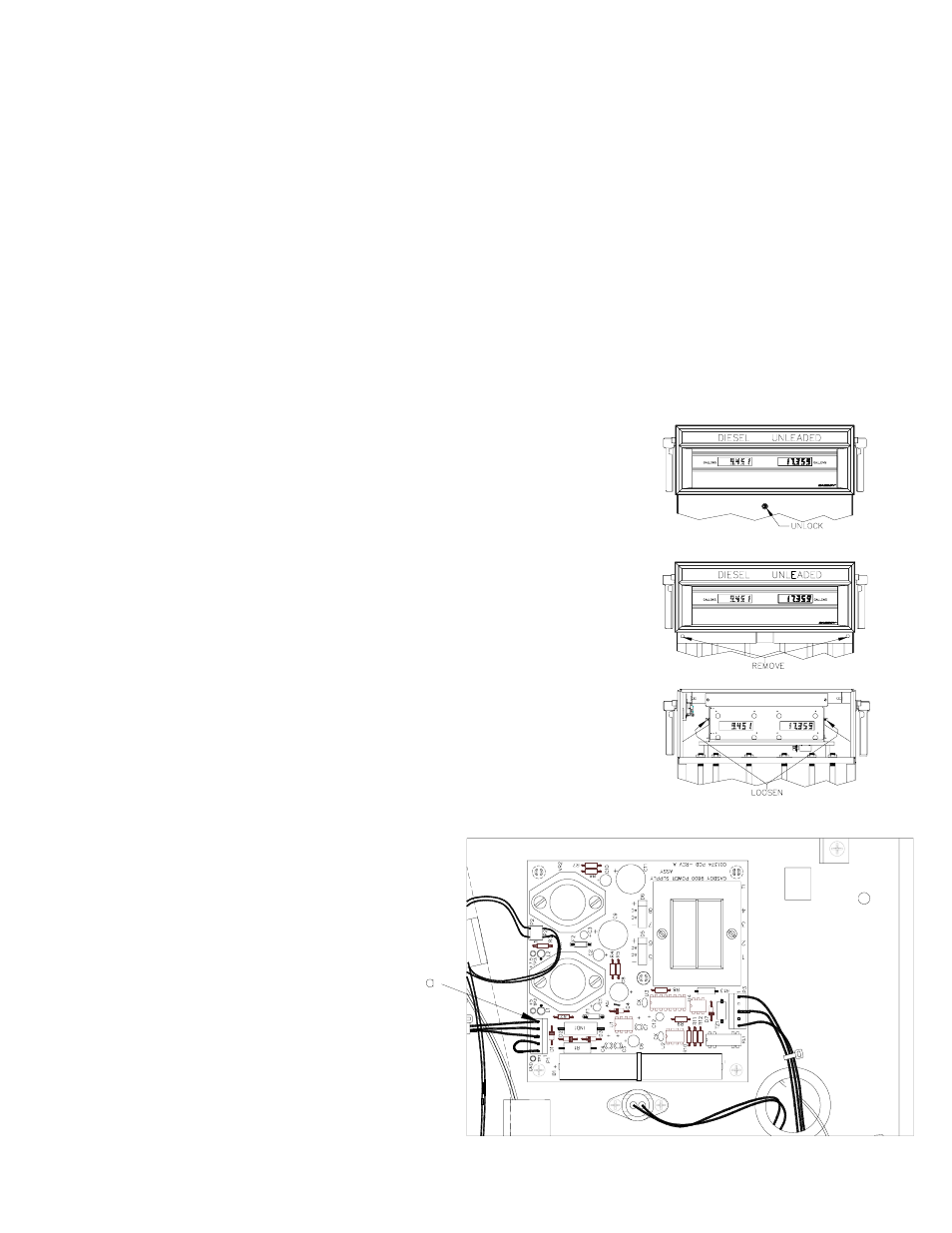
Unlock and remove the front panel.
4.
Remove the two bolts located over the tabs of the bezel assembly. Lift the bezel
assembly upwards and out to remove.
5.
Loosen, and remove if necessary, two screws located on the left and right door
support brackets and pivot the display panel down.
6.
Repeat Steps 3 through 5 on the other side
of the pump.
7.
Pull the connector off P1 (a) on the power
supply. After a few seconds, reconnect
P1.