Gasboy Islander 4-Hose PCU User Manual
Gasboy Hardware
C35552 Rev. 0167
Page 1
INSTALLING AN ISLANDER 4-HOSE PEDESTAL PUMP CONTROL UNIT
This C06653 kit contains all the hardware necessary to install a 4-hose pedestal pump control unit into an Islander pedestal.
This kit includes:
Item P/N
Description
1
C06600
Cage Assy., 3 Slot PCU Card
2
C06591
Cable Assy., DC PWR Ped. PCU
3
C06593
Cable Assy., 4 Relay Control
4
C06567
Cable Assy., PCU Comm.
5
C04037
Screw, #8-32 x 3/8” (Qty 9)
6
C06594
Relay Module Assy. (Qty 4)
7
C02418
Decal, Nos. 1-2-3-4 White
8
C05040
Power Supply Assy.
9
C06595
Cable Assy., AC P/S, Head
Item P/N
Description
10
C08237
Connector, 12-position TB/PG
11
C08528
Connector, 8-position TB/PG (Qty 2)
12
C04035
Screw, #6-32 x 1/4” (Qty 4)
13
068843
Washer, #6 Locking
14
C32731
Plate, Silk-Screened Escutcheon
15
067126
Washer, #8 PLTD (Qty 3)
16
068842
Washer, #8 Locking (Qty 9)
17
C02293
Decal, Nos. 1-2-3-4 Black
18
C06757
Surge Protector Assembly
1.
Switch off power to the Islander and disconnect all AC power to the unit. Remove the screws that secure the side
covers on the pedestal and remove the covers.
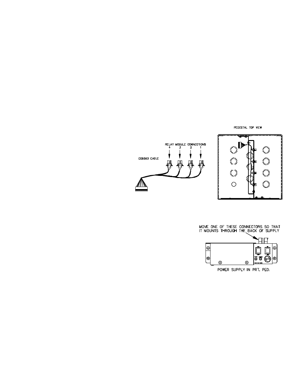
2. Install the C06593 Relay Control Cable. This
cable has four connectors in graduated
lengths. On the left side of the pedestal, start
with the longest of the four connectors and
attach it to the rightmost square opening in the
support bracket so that the pins are pointing
away from the center of the pedestal. Repeat
for all connectors from longest to shortest.
Run the cable between the two support
brackets to the card cage side. See drawing
at right.
3.
Install the C05040 power supply using four of the C04037 screws and 068842 locking washers. Do not tighten the
corner screw that holds the power supply cover, as you will need to remove the cover to connect the cable to the card
cage assembly.
If you are installing the power supply into a printer pedestal, one of the AC
power connectors on the top of the supply must be moved so that it is
mounted through the back of the supply. On the printer pedestal, there is a
connector for the AC power coming from terminal block TB2. It must go
through the opening in the mounting bracket and plug into the moved
connector at the back of the power supply before the supply is installed.
4.
Install the C06594 relay module assemblies. Connect the cables to the relay control cable installed in Step 2. Apply
the numbers from the C02418 decal to the relay modules. Numbering is 1 2 3 4 from left to right.
5.
Install the C06600 card cage assembly using three of the C04037 screws, 067126 washers, and 068842 locking
washers. Connect the relay control cable 12-pin connector to P2 of the motherboard in the card cage assembly.
6.
Install the C06591 DC power cable. Connect one end to P1 on the motherboard in the card cage assembly. Remove
the power supply cover. Connect the other end of the cable to P1 of the power supply board. Replace power supply
cover.