Gasboy CFN Islander II User Manual
Page 36
Advertising
System Components Wiring
03/07/03
3-9
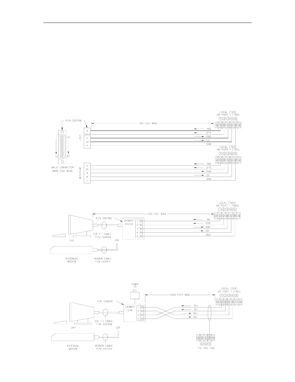
PORT COMMUNICATION WIRING
The following diagrams show the pin-to-pin layout of the possible wiring schemes for the Islander
ports. Each port may be wired for any of the wiring schemes provided the installation
requirements are met as outlined at the beginning of this section in the Communication
Requirements. In the drawings below, the LOCAL terminal block (TB3) is connected to Port 0 of
the Islander II.
NOTE: To insure the necessary signals and proper operation, external modems used in dial-out
or bank network applications must use the remote or Port 2 terminal block (TB4).
Local Port Wiring
RS-232 - D Connector
RS-232 - GASBOY Termination Box
RS-422 - GASBOY Short Haul Modem
Advertising