Gasboy Profit Point Power Supply User Manual
Gasboy Hardware
C36061
Rev. 9180
REPLACING THE PROFIT POINT POWER SUPPLY (KIT C07465)
This instruction sheet details the procedure for replacement of the Profit Point power supply. Kit C07465 contains the
following:
C09864
Power Supply
C07466
Cable Assembly, IPC
C36060
Bracket, Power Supply mounting
039069
Nut, Hex Keps, #6-32
Important:
This new supply will NOT supply power to the C01264 IPC monitor. You must use the C09502
monitor (part of C06821 kit) with this new supply. If you do not have the correct monitor, do not
proceed.
1. Switch off power to the Profit Point unit and unplug the AC power cord. Remove the 5 screws (2 in the back, 3 in the
front) that hold the terminal together and carefully remove the top half. Carefully stand the top on the left side of the
unit without pulling on the cables.
NOTE: All electrostatic precautions must be observed when replacing any electronic component. If needed, move
the Profit Point to a static-free work station and use a wrist strap while working on the assembly.
2. Disconnect the power supply cables from the CPU board and the disk drives. When disconnecting the power cable
from the hard drive, you may need to remove the mounting screw behind the connector. Disconnect the cable to the
AC power switch by sliding the spade terminals off the switch. Disconnect the supply ground wire.
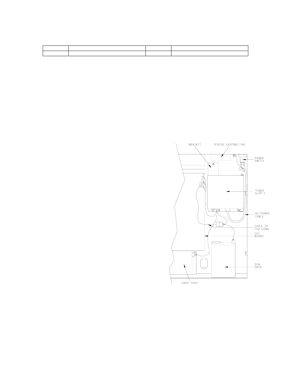
3. Remove the 4 screws that hold the existing power supply and
remove the power supply. Remove the existing fan from the
back of the unit.
4. On the new supply, remove the power switch (if present) from the
AC cable. Attach the mounting bracket to the new supply. Install
the supply into the unit and secure using 3 of the screws removed
in Step 3.
5. Connect the power supply cables to the disk drives and CPU
board. If you removed a screw to disconnect the hard drive
power cable, replace it now. Use the cable supplied with the kit
to connect one of the unused drive connectors to the PS2
connector on the CPU board.
6. Connect and secure the AC ground wire from the supply to the
chassis.
7. Connect the wires to the AC power switch. In addition to the
ground wire, there are four wires in the cable from the supply.
Two of them connect the supply to the AC power switch and two
are unused. Power supplies may not be wired consistently, so
the wiring sequence may differ.
Connect the black wire from the supply to the side of the switch
that has the black input wire connected to it. Connect the white
wire to the side with the white input connected to it. Plug in the
AC power cord and switch the terminal on. If the unit powers up
and starts to boot, the supply has been installed correctly. Switch
unit off and proceed to Step 8.
If it does not work, switch the terminal off and unplug the AC power cord. Disconnect the black and white power
supply wires from the switch. Connect the brown wire from the supply to the side of the switch that has the black input
wire connected to it. Connect the blue wire to the side with the white input connected to it. Plug in the AC power cord
and switch the terminal on. If the unit powers up and starts to boot, the supply has been installed correctly. Switch
unit off and proceed to Step 8.
8. Replace unit top and secure with screws removed in step 1. Switch terminal on and verify unit is operational.