Gasboy 9820 User Manual
Gasboy Hardware
C36023
Rev. 9032
INSTALLATION INSTRUCTIONS FOR 9820/2620 HEATER KITS
120VAC (C06719)/240VAC (C06720)
Locate and identify the following parts in the Heater
Kit.
QTY
PART NO. DESCRIPTION
1
C06677
Cable Assy, Heater 120vac
or
1
C06721
Cable Assy, Heater 240vac
2
067165
Washer, Sq. Fiber
2
C04037
Screw, 8-32 X 3/8
2
067126
Washer, #8 Plated
2
C08759
Screw, #6-32 X 3/8
1
C02827
Bushing, Snap-In 1”
2
067765
Washer, Fiber, 11/64 X 5/16 X 3/64
For Factory Installation complete steps 7-10. For field
installation complete all steps.
1. Turn off the circuit breakers supplying power to the
unit.
2. Unlock door and remove. Loosen two knurled
screws on display and lower display.
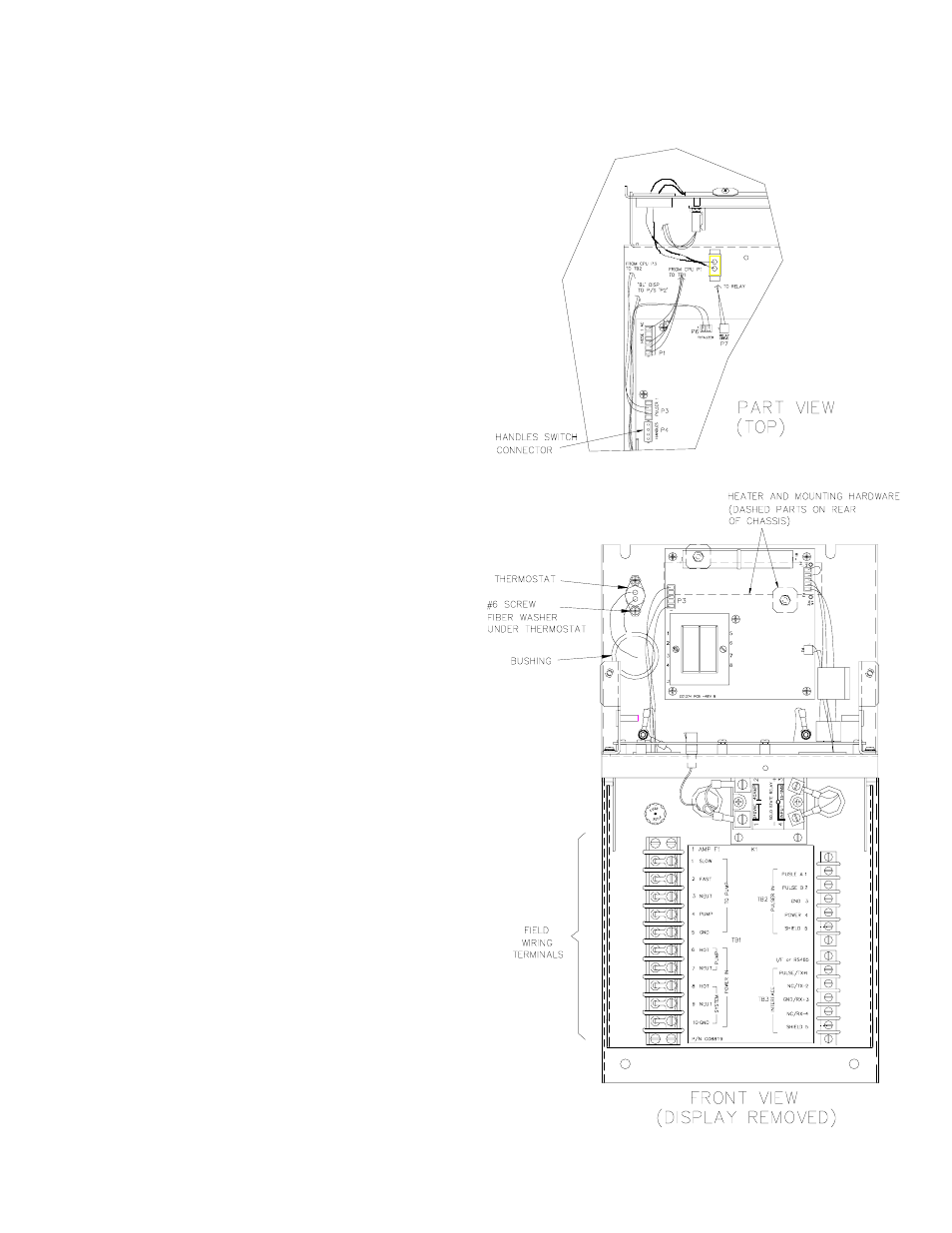
3. Locate and disconnect Handles switch connector
on left front of the CPU PCB.
4. Label and disconnect all field wiring.
5. Remove chassis from housing by loosening and
removing four (4) nuts and washers.
6. Carefully remove chassis (bottom first) to clear
handle mechanism.
7. Install bushing in chassis and remove backing and
mount heater strip on rear of chassis using (2)
square fiber washers and #8 hardware.
8. Feed cable (thermostat and connector) through
bushing and install thermostat using (2) #6 screws
and round fiber washers (mount washer under
thermostat)
9. Connect 2-position connector to chassis connector
located in center rear of the chassis.
10. Assemble chassis, install chassis in housing and
re-connect Handles switch connector. Hinge
display to upright position and tighten two (2)
knurled screws.
11. Reconnect field wiring, install and lock front panel.