Gasboy 25 User Manual
Page 5
MDE-4452 Pump Models 25 and 26 Mounting Instructions · April 2005
Page 5
INSTALLATION
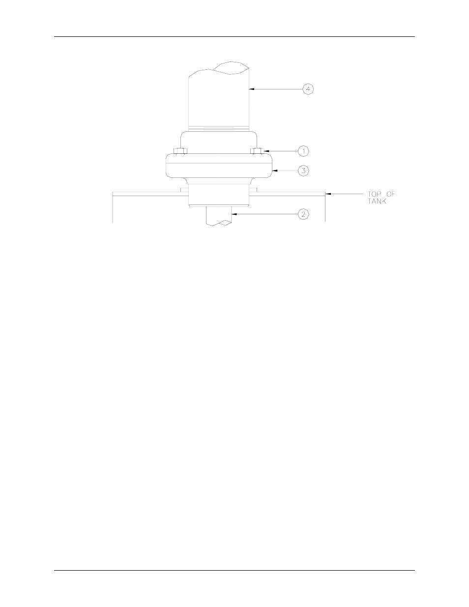
1.
Remove four (4) capscrews (item 1).
2.
Separate pumping unit (item 4) from base flange (item 3).
3.
Assemble suction pipe (item 2) to base flange (item 3).
4.
Install base flange and suction pipe to 2" tank mounting socket.
5.
Position O-Ring seal to pumping unit (item 4).
6.
Position pumping unit (item 4) in base casting (item 3) and mount with four (4) capscrews (item 1).
7.
For Model 25 only: Located in top of box is one cloth bag containing 2 screws (1/4 x 20 x 3/4 oval
head) and one nozzle hanger (P/N 003673). Align nozzle hanger with lower half of pump handle
(pump handle in off position). Insert two screws and tighten.
OPERATION
Before starting pump, press RESET button all the way down to reset the register to zero. Remove nozzle
and turn the switch lever to start pump.
Built-in check valve keeps pump fully primed for immediate use at all times. Nozzle provides controlled
delivery of up to 30 GPM of accurately measured product. Switch lever is designed to prevent nozzle
from being holstered until pump is turned off.
GASBOY