Gasboy 1000 Series Installation User Manual
Series 1000 installation quotation guide, Hardware description
C35294 Rev. 03/07/03
Page 1
Series 1000
Installation Quotation Guide
(For Quotation Use Only - Do Not Install From This Guide)
This document is provided as a guide for quoting the installation of a Series 1000 System. Component location, power, wiring, and
conduit requirements can be calculated from this guide. The Series 1000 Installation Manual (not this guide!) should be used for the
actual installation of the system. GASBOY will not be responsible for installations performed from this guide.
HARDWARE DESCRIPTION
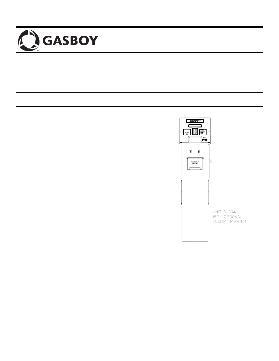
The GASBOY Series 1000 Fuel Management System is a
microprocessor-based fuel control and data acquisition system.
It is available in three types: card, cardless, or FleetKey. It is
totally self-contained in an attractive, weatherized cabinet and
pedestal assembly. The system is Underwriter’s Laboratories
listed and FCC-approved and is designed to be located on the
fueling island convenient to the user.
The user-accessible part of the system consists of a 20-
character liquid crystal display (LCD), which displays
messages to guide the user through operating steps; and a 12-
position keypad containing the keys 0-9, CLR, and ENT,
which is used to enter data, (e.g., personal identification
number (PIN), odometer readings, pump selections, etc.). All
entries, except PIN, are displayed on the LCD for verification.
The card system is available with a magnetic stripe insertion
reader or a static optical card reader; the FleetKey with one or
two key receptacles. A red stop button on the cabinet face
allows the dispensing equipment to be shut down quickly in
case of emergency.
The rear of the cabinet is a hinged door secured with a lock to
prohibit unauthorized access. The one-piece hood can be
removed for total accessibility during servicing and interior
LED indicators help diagnose system problems.
Solid state relays, and manual override switches, which
control power to the fuel dispensing equipment, are located in
the pedestal. The wiring for all equipment connected to the
Series 1000 is terminated in the pedestal. An optional high
speed, bidirectional, serial impact receipt printer can also be
housed within the pedestal. The standard Series 1000 System
controls two hose outlets and can be expanded in two hose
increments to control a maximum of eight hoses. The unit can
be expanded in the field. The system can handle pulsing rates
of dollar (penny per pulse) or quantity (1, 10, 100, 250, 500, or
1000 pulses per unit of product). The pulse rate selection
switch is located in an area sealable by Weights and Measures
for retail applications.
The standard Series 1000 System contains two asynchronous
ports for terminal and/or computer communications. An
optional auxiliary asynchronous port is available for tank
monitor or receipt printer interfacing. All ports may be set to
either RS-232 or RS-422 communications to meet individual
requirements.
A CRT or data terminal with an ASCII character set, or a
computer with the proper interface, is required to
communicate with the Series 1000. The terminal is connected
to the system through one of the two asynchronous
communication ports located in the system cabinet.
Communication is through direct wire, or by dial-up phone
lines using an optional built-in modem. (See Communication
Wiring for specific communication requirements and distance
limitations.)