Gasboy 1000 Series Shift Register Selections User Manual
Gasboy Hardware
C35749
6078
SHIFT REGISTER SELECTIONS ON THE SERIES 1000 MPU PCB
The Series 1000 MPU PCB contains a size selectable shift register which inputs the mag data received from a mag
card. The variable selections of the shift register hardware change the maximum number of characters that may be
accepted into the shift register per card read. There are several versions of Series 1000 software currently being
used in the field. Each software version requires a specific shift register setting on the MPU PCB for optimum
performance.
Determine which software version is used at the site by doing a PR
command or read it off of the ROM label located in the IC socket marked
U21. The software version on the ROM label appears in the format Vx.x.
The number immediately following the V is the version number, for
example, if the label shows V8.1, you have version 8 software, revision
level 1. Use the chart on the right to determine the shift register size for
your specific version of software.
Software
Versions 1-2
Versions 3-6
Versions 7
or higher
Shift Register
32
48
64
Next you need to determine the revision level for the MPU PCB. There is a revision level located in the upper left
corner of the Series 1000 MPU PCB. The revision level is represented by a letter which is silkscreened or
handwritten with black indelible marker. An MPU with a handwritten revision level indicates the board was modified
to include new hardware updates. Important: If you have a Series 1000 MPU PCB with revision level of E or
lower, send it back for exchange with a Rev. G2 or higher MPU PCB.
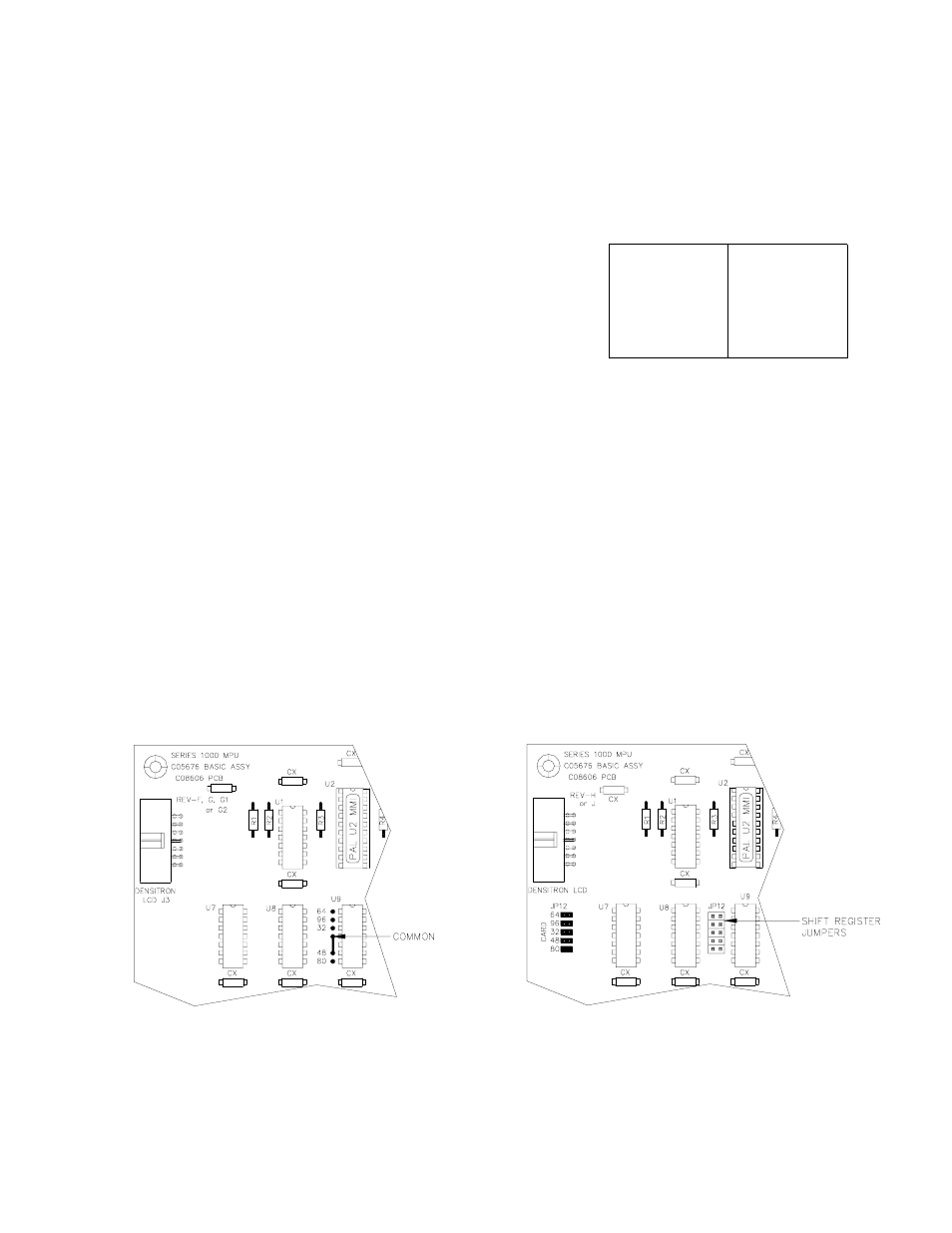
If the Series 1000 MPU PCB is Rev. F, G, G1, or G2,
the shift register is set to 48 through a trace of the
artwork or a jumper wire. This MPU PCB is instantly
compatible with software versions 3-6.
The figure below shows a MPU PCB configured for a
48 shift register. When a shift register of 32 or 64 is
required, the connection between Common and 48
must be cut. If the connection is through an artwork
trace, use an X-acto knife to cut open the trace. Use
an ohmmeter to verify the trace has been opened. If
the connection is through a wire jumper, simply
desolder the side attached to 48. Make the new shift
register connection by soldering a jumper wire
between Common and 32 or Common and 64.
If the Series 1000 MPU PCB is Rev. H or J, a shift
register jumper patch allows the shift register size to
be easily selectable. This MPU PCB is quickly
compatible with all software versions.
The figure below shows the location of the shift
register jumpers (JP12). To the left of the jumpers is
a silkscreen indicating which jumper position
corresponds to each shift register size. For example,
a jumper across the top two pins of the shift register
jumpers will give a shift register size of 64. Simply
place the 2 position jumper on the pins which
correspond to the desired shift register size.