Gasboy 1000 Series TopKAT Report Printer User Manual
Gasboy Hardware
C35854 Rev 7224
Page 1
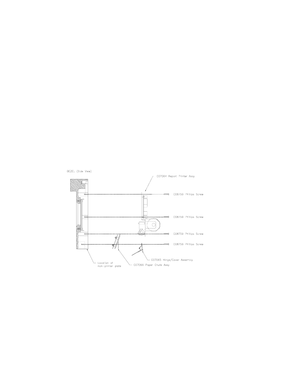
FIELD INSTALLATION OF A SERIES 900 (TOPKAT) REPORT PRINTER KIT
The Series 900 TopKAT report printer kit (C07063, 115V or C07069, 230V) should contain the following parts:
Item
Qty
P/N
Description
1
1
C07064
Report Printer Assembly
2
1
C07065
Hinge/cover Assembly
3
1
C07066
Paper Chute Assembly
4
1
C07067
Heater Assembly (115V only)
1
C07068
Heater Assembly (230V only)
5
1
C35854
Field installation instructions
6
1
C09370
Power Supply, 5V 4.0A
7
1
C09568
Decal “CAUTION HOT”
Item
Qty
P/N
Description
8
2
C02207
Clamp, Ribbon cable
9
2
039069
Nut hex #6-32
10
8
C08759
Screw #6-32 Philips
11
2
C04128
Screw #4-40 Pan Head
12
1ft
027065
Gasket Rubatex R411
13
1
0M0042
Tie Wrap
14
2
C04039
Screw #6-32 x 1/2 Phillips
1.
Unlock and open the front and rear door of the TopKAT.
2.
Turn off the AC power switch located to the right when viewed from the rear of the head.
3.
Remove two C08759 screws holding the non-printer plate to the bezel. Also remove the bottom bezel gasket.
4.
Install the paper chute assembly and hinge/cover assembly and secure them with the two C08759 screws removed
with the non-printer plate. (See the diagram below for proper location and position of the assemblies.)
5.
Install 027065 gasket in place of the gasket removed earlier. (It maybe necessary to trim the gasket to insure a good
seal.)
6.
Install the printer assembly. Align the four screw holes and secure with four C08759 screws. (See diagram below for
proper location and position of the assemblies.)
7.
Remove the power supply cover marked WARNING HIGH VOLTAGE by removing the three screws that secure it.
8. Install
the C09370 power supply into the lower left corner of the power supply chassis assembly, with the 4-position
DC connector to the left and 3-position AC connector to the right. Secure the supply with four C08759 screws.
9.
Attach the two connectors from the printer assembly cable. One connector plugs into J8 on the TopKAT CPU Board;
the other connector plugs into the 4-position DC out. Be sure to put the DC connector through the bushing from left
to right then onto DC output connector. Failure to do this will not allow you to reinstall the power supply cover without
pinching the cable.