Gasboy 4-Hose PCU User Manual
Gasboy Hardware
C35553 Rev. 0167
Page 1
INSTALLING AN ADDITIONAL ISLANDER 4-HOSE PEDESTAL PUMP CONTROL UNIT
This C06654 kit contains all the hardware necessary to add a 4-hose pedestal pump control unit into an Islander pedestal
with an existing pedestal pump control unit. This kit includes:
Item P/N
Description
1
C06600
Cage Assy., 3 Slot PCU Card
2
C06590
Cable Assy., DC PWR Ped. PCU
3
C06593
Cable Assy., 4 Relay Control
4
C06608
Cable Assy., PCU Comm.
5
C04037
Screw, #8-32 x 3/8” (Qty 4)
6
C06594
Relay Module Assy. (Qty 4)
7
C02952
Decal, Nos. 5-6-7-8 White
8
C08237
Connector, 12-position TB/PG
Item P/N
Description
9
C08528
Connector, 8-position TB/PG (Qty 2)
10
C04035
Screw, #6-32 x 1/4” (Qty 4)
11
068843
Washer, #6 Locking
12
C32731
Plate, Silk-Screened Escutcheon
13
067126
Washer, #8 PLTD (Qty 3)
14
068842
Washer, #8 Locking (Qty 4)
15
C02293
Decal, Nos. 1-2-3-4 Black
16
C06757
Surge Protector Assembly
1.
Switch off power to the Islander and disconnect all AC power to the unit. Remove the screws that secure the side
covers on the pedestal and remove the covers. Switch off AC and battery power on the PCU power supply.
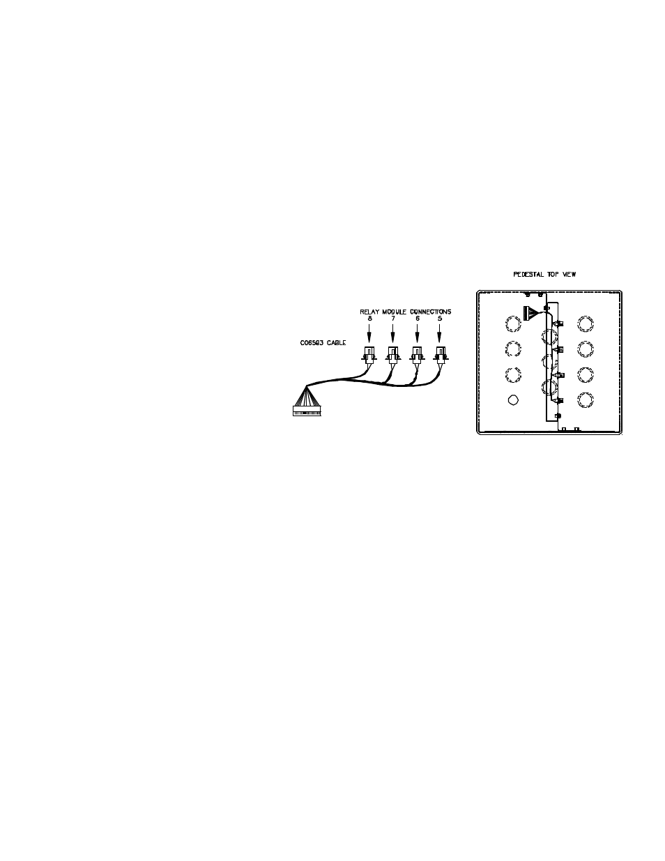
2. Install the C06593 Relay Control Cable. This
cable has four connectors in graduated
lengths. On the left side of the pedestal,
start with the longest of the four connectors
and attach it to the rightmost square opening
in the support bracket so that the pins are
pointing away from the center of the
pedestal. Repeat for all connectors from
longest to shortest. Run the cable between
the two support brackets to the card cage
side. See drawing at right.
3.
Install the C06594 relay module assemblies. Connect the cables to the relay control cable installed in Step 2. Apply
the numbers from the C02952 decal to the relay modules. Numbering is 5 6 7 8 from left to right.
4.
Install the C06600 card cage assembly using the three C04037 screws, 067126 washers, and 068842 locking washers.
Connect the relay control cable 12-pin connector to P2 of the motherboard in the card cage assembly.
5.
Remove cover from the power supply. Remove the DC power cable that connects P1 of the power supply to P1 of the
motherboard on the existing PCU card cage. Install the C06590 DC power cable. Connect the cable from P1 of the
power supply to P1 of the existing PCU card cage and P1 of the newly installed card cage. Replace power supply
cover.
6.
On the new PCU CPU board, set the address switches to match to site’s configuration. Set the jumpers on the new
Pump I/O board to match the pulsers being used. Refer to the Islander II Installation Manual C35963. Install the
C32731 escutcheon plate using the C04035 screws and the 068843 washer. The washer goes on the screw closest to
TBR connector. Apply the number 2 of the C02293 decal to the escutcheon plate.
7.
Remove the PCU Comm. cable that connects P3 of the RS485 Protection board to TBK on the existing Pump I/O
board. Install the C06608 PCU comm. cable from TBK on the existing Pump I/O board to TBK on the new Pump I/O
board and to P3 on the RS485 Protection board. If the unit has 2 protection boards, the cable connects to the upper
board.