Powermax, Maintenance, Service manual – Hypertherm Powermax600 Service Manua User Manual
Page 33
MAINTENANCE
3-7
powermax
600
Service Manual
M1
Cap Switch
Start Switch
TS1
TS2
~
~
-
+
Board
Power
PCB2
S1
On Rear of Board
Start
LED6 LED7 LED8
Power
O.K.
Low Volt
Low Pres
Cap Off
Over Temp
Bridge
Input
D18
Diode
Regulator
Switch (gas)
Pressure
PS1
Valve (gas)
Soleniod
V1
Filter
Air/Gas
Source
Air/Gas
to
Torch
LEDs
Gas Test
Current Adjust
PCB3 Control Board
sensors
xfer
Nozzle
Work
IGBT
PA
Q3
xfmr
Power
T2
Diode
Output
D2
TB1
~
~
-
+
Workpiece
Electrode
Torch
Module
IGBT
Q2
L2
Pilot Arc
Switch
Designator
Component
D18
..................
Input diode bridge
D2
....................
Output diode
L2
.....................
Output choke inductor
M1
....................
Fan
PCB2
................
Power board
PCB3
................
Control board
PS1
..................
Pressure switch
Q2
....................
IGBT module
Q3
....................
Pilot arc IGBT
S1
.....................
Breaker
TB1
..................
T
erminal block
TS1
..................
Heatsink temperature sensor
TS2
..................
T
ransformer temperature sensor
T2
.....................
Power transformer
V1
.....................
Solenoid valve
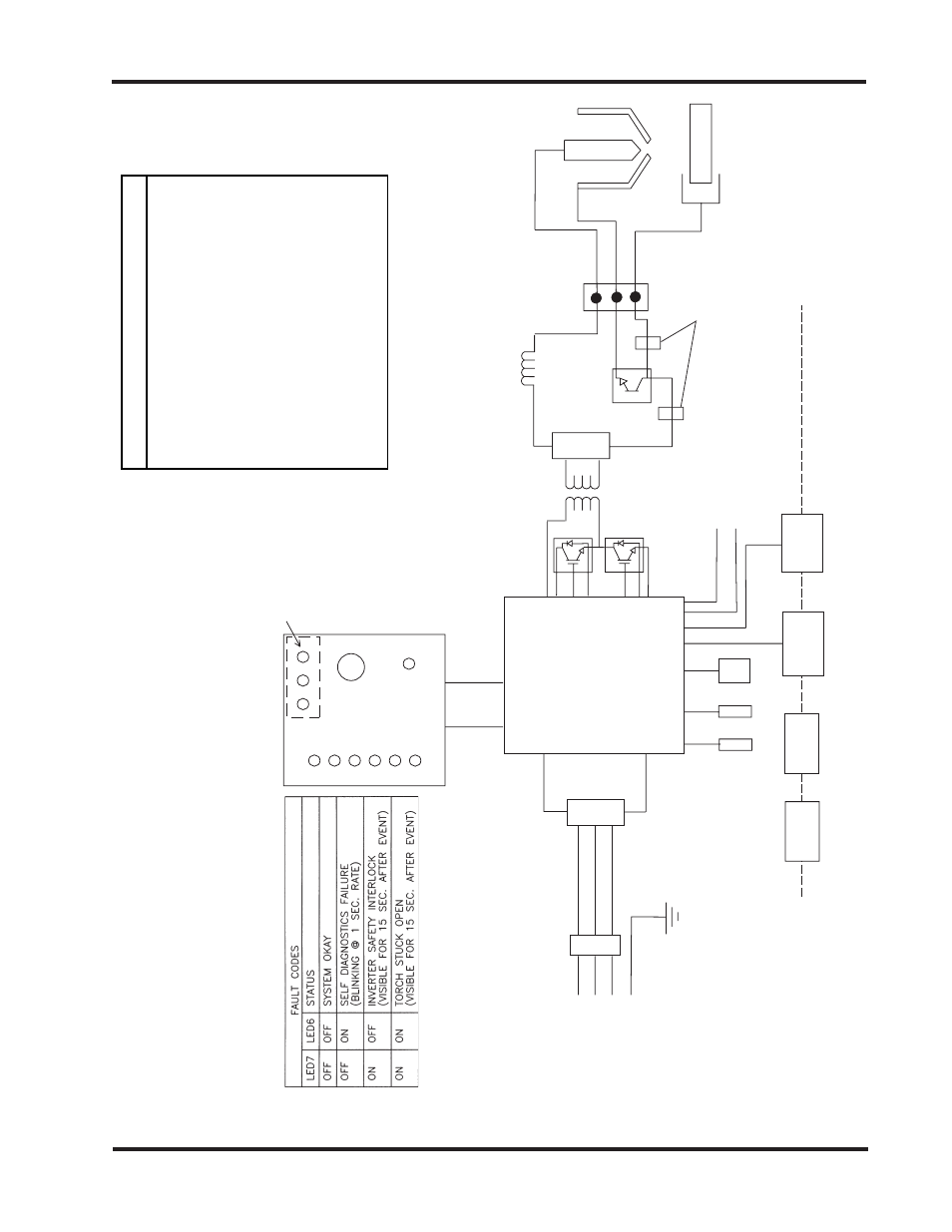
Figure 3-2.2 Powermax600 208-240/480 Volt Block Diagram
10-99