Powermax, 480v – Hypertherm Powermax600 Service Manua User Manual
Page 37
MAINTENANCE
3-11
powermax
600
Service Manual
PMX600-SM.01
2.5M
208V - 240V
300-500K
>50M
230V and 400V
3.5 - 4.5M
>50M
480V
>50M
Resistance Checks
All resistance values were taken with the power cord disconnected and all internal power supply
wires attached. Perform Visual Inspection - Internal before continuing in this section.
•
If your resistance values are not close to the values given in this section, isolate the problem
by removing wires attached to the resistance check points or component until the problem is
found.
•
After the problem has been located and repaired, refer to the Sequence of Operation flow
diagram in this section to test the power unit for proper operation.
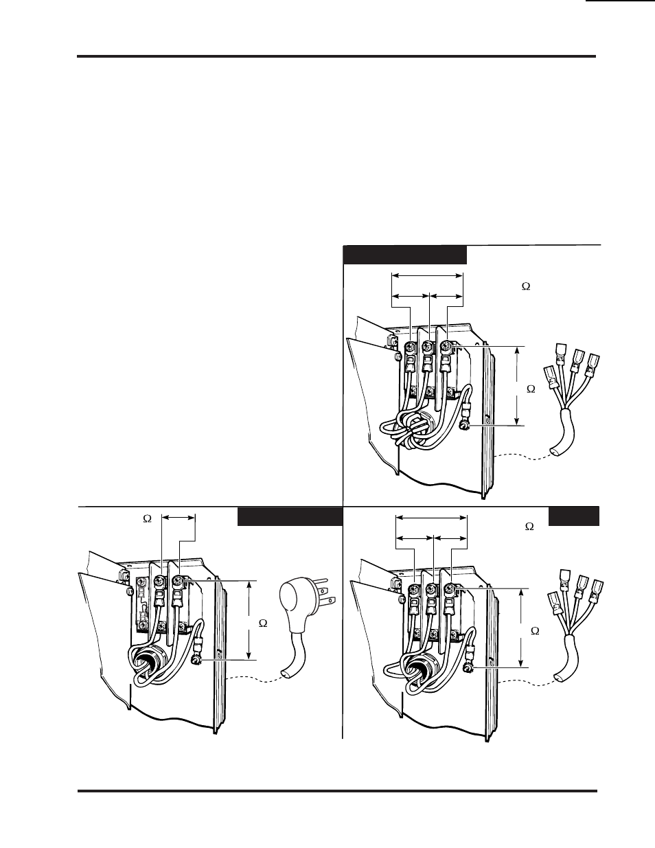
Resistance Check #1 - Figure 3-3
1. Turn switch ON (power disconnected).
2. Check resistance across input leads.
3. Check resistance from
input leads to ground.
Figure 3-3 Resistance Check #1 - Across Input Leads and Input to Ground
10-99