Appendix 2: wiring diagrams – Infloor Electric Cable Series 386 User Manual
Page 22
IOM-INF-Cable 1434
22 of 36
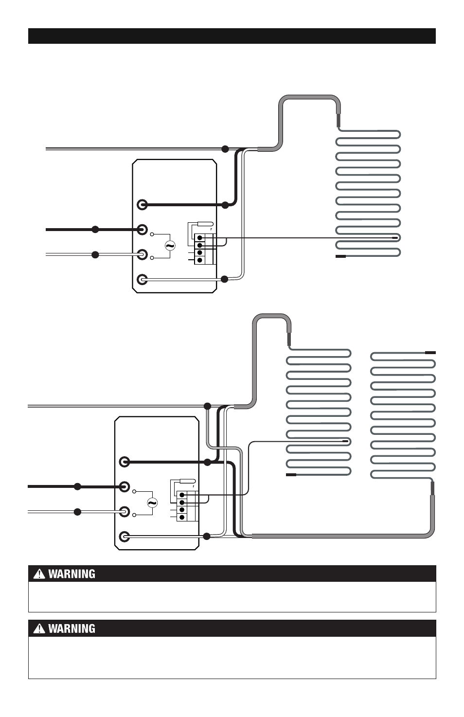
120/240 VAC
Infloor Control
120 VAC or 240 VAC
Sensor Wire
(no polarity)
Two or more 120 VAC or
240 VAC Heating Cables
(maximum 15 amps)
Infloor Cable
Infloor Cable
Load 1
Line 1
Line 2
Black
Black
Black
Ground
White
White
White
Bus
Sensor
A
B
Load 2
120/240 VAC
Infloor Control
120 VAC or 240 VAC
Sensor Wire
(no polarity)
120 VAC or
240 VAC Heating Cable
(maximum 15 amps)
Infloor Cable
Load 1
Line 1
Line 2
Black
Black
Black
Ground
White
White
White
Bus
Sensor
A
B
Load 2
Appendix 2: Wiring Diagrams
120/240VAC Control Wiring Diagrams
Typical Wiring for multiple Infloor Electric
Cables with Infloor thermostat (120/240VAC)
20-amp circuit.
Typical Wiring for one Infloor Electric Cable
with Infloor thermostat (120/240VAC)
20-amp circuit.
Make sure 120 VAC is supplied to 120 VAC cables and 240 VAC is supplied to 240 VAC
cables. Otherwise, dangerous overheating and possible fire hazard can result.
All electrical work must be done by a qualified licensed electrician in accordance with local
building and electrical codes, and the National Electrical Code (NEC), especially Article
424 of the NEC, ANSI/NFPA70 and Section 62 of CEC Part 1.