K-Patents PR-33-AC User Manual
Page 12
6
PR-33-AC instruction manual
Document/Revision No. Rev. 1.02
Effective: June, 2014
Note: The connection will not work if the computer and the refractometer have exactly
the same IP address.
When the network settings of the instrument (and/or the computer) have been con-
figured according to the instructions above, the next step is to test the connection as
instructed below in Section 2.3.5.
2.3.4 Configuring a network of refractometers
In case there are more than one Sanitary OEM Refractometer in a network, their IP
addresses have to be configured manually as the factory default will not work.
If the Sanitary OEM Refractometer is to be connected to a factory network, consult the
network administrator for the correct settings.
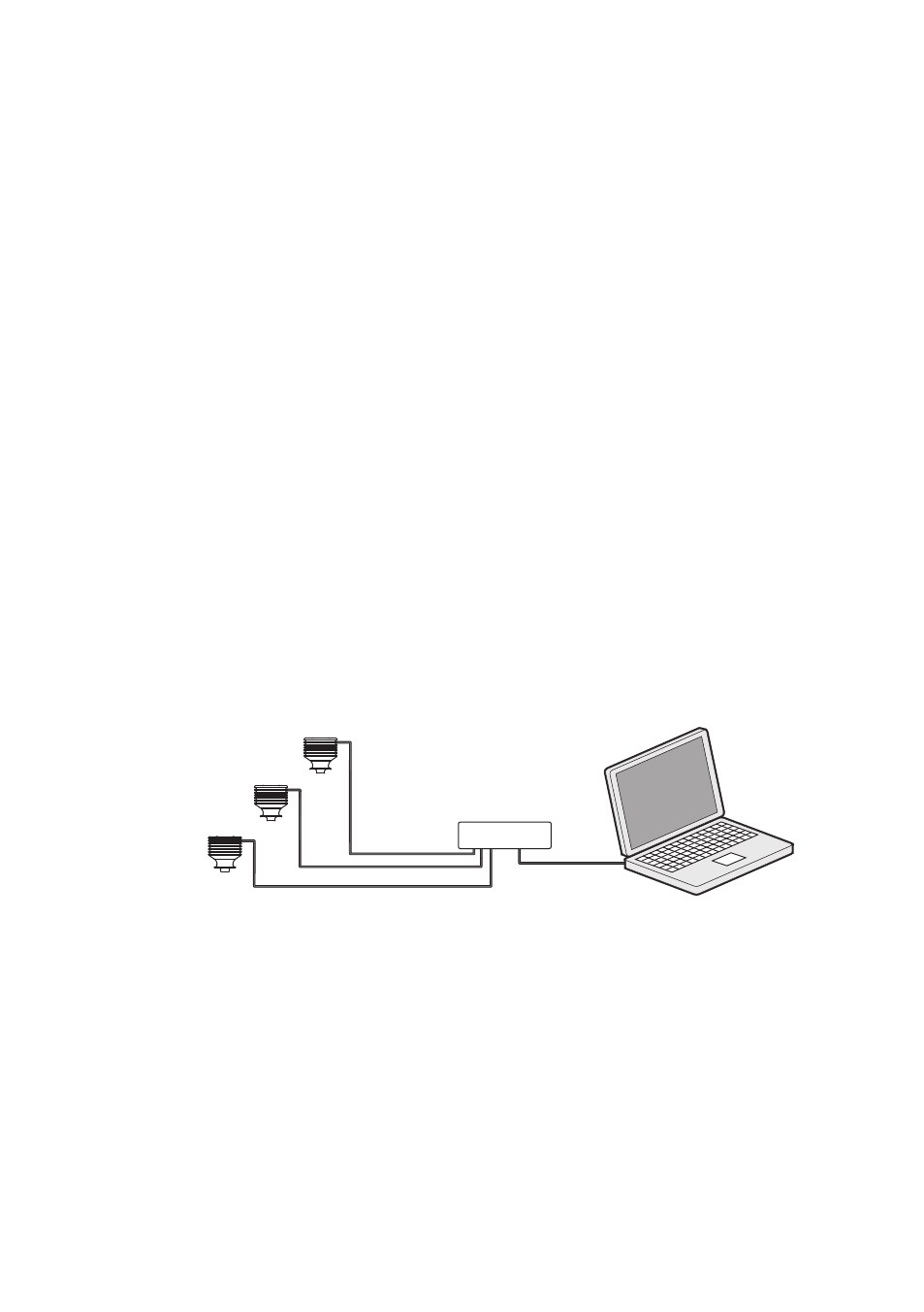
If the network is a stand-alone network with only one Sanitary OEM Refractometer and
one or more computers with no connection to any other network, then the IP addresses
can be chosen rather freely. One possibility is to number the instruments so that they
all have 192.168.33.x addresses so that every computer and instrument has a different
number x between 1...254. The subnet mask (or netmask) is in this case 255.255.255.0
(see figure 2.6).
Hub/Switch
IP = 192.168.33.1
IP = 192.168.33.2
IP = 192.168.33.3
IP = 192.168.33.100
netmask = 255.255.255.0
Figure 2.6
A network of Sanitary OEM Refractometers.
Note: There are no settings for subnet mask, default gateway or name servers in the
Sanitary OEM Refractometer, as these settings are not required.
2.3.5 Testing the Ethernet connection
When the Sanitary OEM Refractometer is connected to a switch, the corresponding link
light should light up in the switch.