3 refractometer wiring – K-Patents PR-33-AC User Manual
Page 17
3 Refractometer mounting
11
© Copyright K-Patents 2014. All rights reserved.
The diameter and form of the pipe and the process temperature all affect the measure-
ment and need to be taken into account. (See figure 3.1)
1. If the process pipe diameter varies, select the position with the smallest diameter
(and accordingly highest velocity). Then the prism stays clean better.
2. If the refractometer is used in a feed-back control loop, make the time lag short. E.g.
when a dilution valve is controlled, mount the refractometer close to the dilution
point. However, make sure complete mixing has occurred at mounting location.
3. If the temperature varies along the process pipe, select the position with the highest
process temperature. That minimizes the risk of coating, because higher tempera-
ture means higher solubility and also lower viscosity.
4. Often the position with the highest process pressure (= after pump + before valve)
has favorable flow conditions without sedimentation or air trapping risks.
5. The refractometer should be conveniently accessible for service.
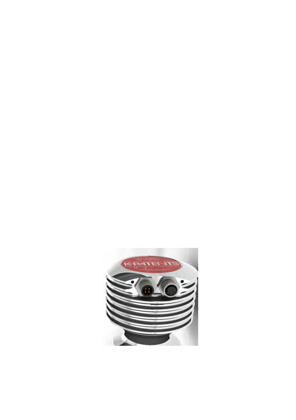
3.3 Refractometer wiring
There are two M12 connectors in the Sanitary OEM Refractometer sensor. The A-coded
male sensor is for power supply and milliamp output signals. The D-coded female con-
nector is for the Ethernet connection.
Figure 3.2
Connectors on the Sanitary OEM Refractometer
Please see the wiring drawing (figure 3.3) for wiring instructions.