Kreg PRS1015 Precision Router Table Fence User Manual
Page 8
Assembly
8
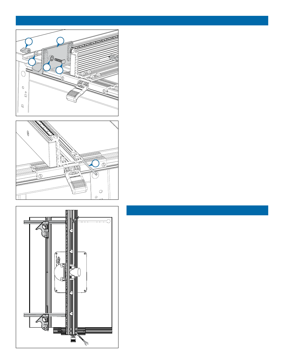
Hardware for this section is in HARDWARE PACK #5.
Assemble the bit guard (28) with T-bolts (29), spacers (30), brass
fl at washers (31), and T-knobs (32). Slide the T-bolt heads into the T-slot
at the top front edge of the fence extrusion, center the guard on the
router-bit cutout, and tighten the knobs.
Align and square the fence
9
To store the jointing rods (33), slide them into the round channel at
the back edge of the fence extrusion base fl ange. (See Jointing
under the section Using Your Router Table Fence.)
1
Using a combination square as a gauge, align the fence parallel to
the miter-gauge slot. Lock the clamp block and tighten the ¼-turn
fence lock. Re-check the parallel alignment and then tighten the hex-
head machine screws that secure the fence extrusion to the clamp block
assembly. Release the fence, slide it back and forth on the mounting rail,
and lock it in place. Verify the parallel adjustment.
30
31
33
28
29
32