C h 1, N o t 4 2, O f f – LSC Lighting Redback Operators Manual User Manual
Page 13: C 1 l 4 2, C 3 b 4 4 0
Redback Dimmer
Basic Menu
Operator Manual V1.2
LSC Lighting Systems (Aust) Pty. Ltd
Page 11
5.2 MIDI Address Allocation [MIDI]
Sets the MIDI addresses for controlling
Redback dimmers.
Dimmers are controlled by Note-On, Note-Off
and Velocity messages from a block of six or
twelve adjacent MIDI Notes starting from the
Channel and Note set from this menu.
Levels set by MIDI control are combined on a
highest-takes-precedence basis with levels from
DMX512, the internal scene memories and the
internal chaser.
Selecting this menu displays the current MIDI
Channel controlling the Redback dimmer or the
current MIDI Note controlling dimmer 1.
In MIDI operating mode, the dimmers are
automatically allocated sequential notes
following the start note. (eg. If the start note is
set to 42, then dimmer 1 will be allocated to
MIDI note 42, dimmer 2 will be allocated to MIDI
note 43, dimmer 3 will be allocated to MIDI note
44, etc).
In this screen:
The
Left and Right arrow keys switch
between:
• selecting the MIDI Channel
C H 1
• selecting the MIDI Note to control
dimmer 1.
N O T 4 2
The
Up and Down arrow keys switch
between:
• setting the MIDI Channel number
(Range 1-16).
• setting a Note number where all
dimmers can be allocated to a valid
Note (Range 0-122 for 6 channel
dimmers or 0-116 for 12 channel
dimmers).
5.3 Scene Setting [SCENE]
Edits and activates a single static scene for
situations where a control system is not
available. Upon exiting the menu, this scene is
automatically saved in memory and will be
recalled when the dimmer is powered on.
Levels set in this scene are combined on a
highest-takes-precedence basis with levels from
the advanced scene memories, DMX512
control, the internal chaser and the optional MIDI
interface.
The Scene function is also useful where some
dimmers are required to be held at a minimum
level independently of other control settings.
Applications include dimming musician's lights, a
follow spot, the spot on the lectern or important
sponsor signage.
The default setting for the scene is off.
In this screen:
The
3 Flip key switches between text and
graphical modes on the LED display.
The
Left and Right arrow keys step
between:
• enabling and disabling scene output
O F F
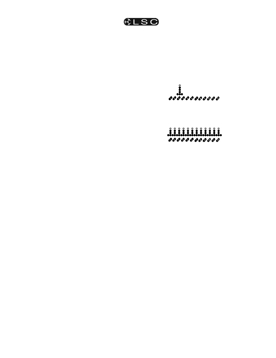
• selecting each dimmer for setting
C 1 L 4 2
or
(12 channel display shown)
• selecting all dimmers for setting.
A L L C H
or
(12 channel display shown)
The
Up and Down arrow keys increase or
decrease the selected dimmer or dimmers.
In All Channel mode, each dimmer increments
or decrements by the same amount, regardless
of its starting level.
5.3.1 SCENE Menu LED
If the scene is active, the SCENE
W menu LED
gives a short double-flash when Redback is
displaying the default status screen.
5.4 Chase Mode [CHASE]
Activates and controls the internal chase effects
generator.
Redback has six inbuilt chase effects patterns
(c1-c6) that may be varied in replay speed
between 10 and 900 beats (steps) per minute.
Levels generated in chase effects are combined
on a highest-takes-precedence basis with levels
from scene memories, DMX512 control and the
optional MIDI interface.
The Chase generator is useful where a repeated
pattern of lights is needed without requiring an
external control system. Upon exiting the menu,
chase settings are automatically saved in
memory and will be recalled when the dimmer is
powered on.
Applications include displays, signage and
parties.
In this screen:
The
Left and Right arrow keys step
between:
• enabling and disabling chase effects.
O F F
• selecting the current chase effect.
c 3 B 4 4 0