Rdm id – LSC Lighting Redback Operators Manual User Manual
Page 6
Installation
Redback Dimmer
Operator Manual V1.2
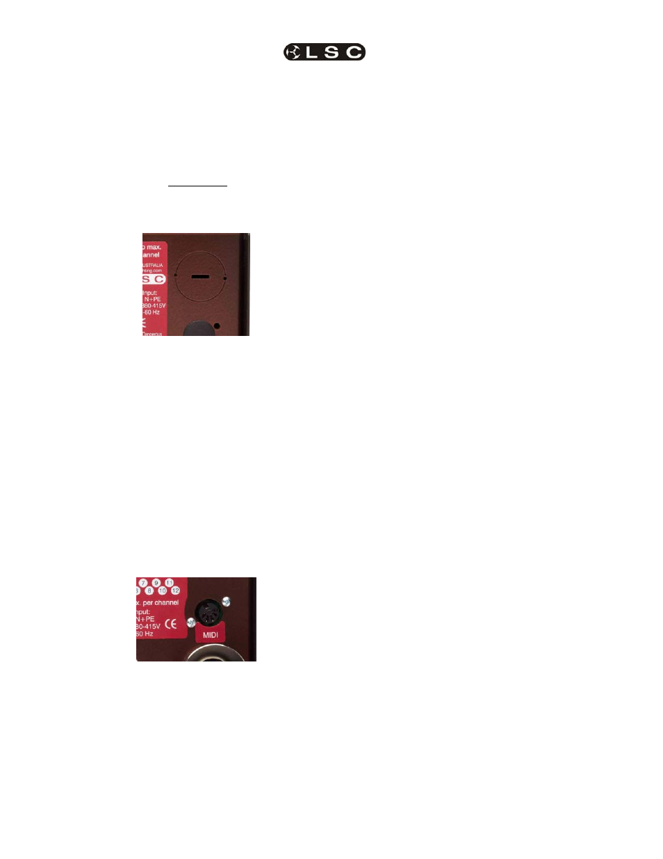
1.10 Power supply entry
6 channel Redbacks are supplied with a cable
knock-out entry as shown in the picture below. A
metal clamping gland is also supplied to clamp
the input power cable to the dimmer. To remove
the knock-out, use a flat blade screwdriver,
insert in the slot provided and twist out the metal
disk. Remove the bottom cover of the dimmer, fit
the cable gland, feed the power input cable
through and terminate to the screw terminals
inside the dimmer.
Both Screw Terminal 6 channel and 12 channel
variants also can have their power cable fitted
as detailed above. Only the metal cable gland is
supplied with the dimmer.
12 channel 2RU Redbacks are supplied with
the power cable and gland already fitted.
12 channel 4RU Redbacks are supplied with a
power cable and metal gland, but not fitted as
you have up to 6 different locations for power
cable entry to the dimmer.
1.11 MIDI input (optional)
A 5 pin DIN MIDI IN (Musical Instrument Digital
Interface) input socket allows any MIDI controller
to set dimmer levels using note ON/OFF and
note velocity values.
1.12 RDM
The Redback allows the viewing of and remote
setting of all menu functions via any RDM
compatible controller.
Functions that can be viewed and controlled are:
• DMX512 start address
• Riggers
Scene
• Chases
• Test
Channel
• Minimum and Maximum levels
• Channel Curve selection
• DMX512
Softpatch
• DMX
Snapshot
• Scene Control and editing
• Reset
In addition the LED display of the Redback
flashes
RDM ID
when asked to identify itself by an RDM
controller.
RDM will also allow the identifying (discovery) of
the device which can include manufacturers
name, model type, number of channels used
and any user programmed name for the device.