1 mounting options, 2 electrical installation, 3 connecting dmx512 and rdm – LSC Lighting Redback Operators Manual User Manual
Page 7: 4 connecting midi (optional)
Redback Dimmer
Meet the Redback
Operator Manual V1.1
LSC Lighting Systems (Aust) Pty. Ltd
Page 5
2 I n s t a l l a t i o n
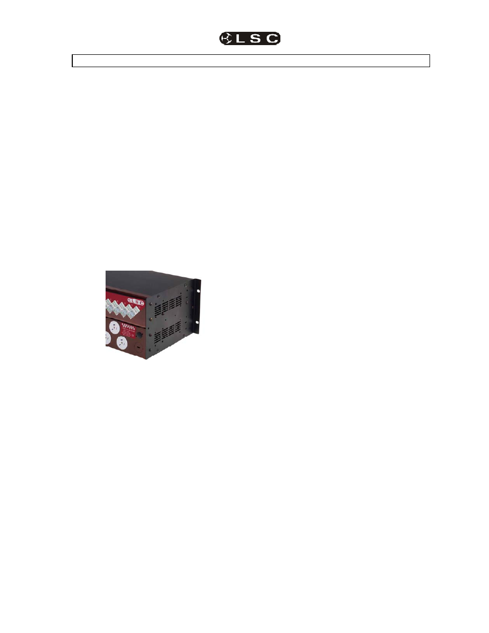
2.1 Mounting Options
Redback may be installed in different
configurations to suit a range of applications.
2.1.1 Rack Mounting
The 2RU versions of Redback are designed for
installation in standard 19" equipment racks,
touring cases, or rack sleeves, where access is
available to both the front and rear of the rack
cabinet.
The 4RU versions are designed for installation in
standard 19" equipment racks, touring cases, or
rack sleeves, where access is available only
from the front of the rack cabinet.
Each Redback should be fixed to the equipment
rack by a minimum of four screws.
2.1.2 Wall Mounting
Reversing the side panels on 4RU versions
allows the rack ears to be used as wall mounting
brackets.
Note: Only change one side panel at a time as
the side panels hold the front panels and
chassis together. Each Redback should be fixed
to the wall mounting frame by a minimum of four
fixing screws or bolts.
2.1.3 Free Standing
All dimmer variants have four rubber feet
installed on the base for floor, bench or shelf
mounting.
2.2 Electrical installation
2.2.1 Safety
All electrical work must be carried out by a
suitably trained and qualified electrical
technician.
2.2.2 Power Supply
The Redback dimmer must be fed from a
suitably rated external protected and limited
power source.
In three phase installations the supply wiring and
overload protection should be suitable for loads
of up to 40 Amps per phase for 12 channel
dimmers and 20 Amps per phase for 6 channel
dimmers. The supply must be in "wye" or "star"
configuration with a neutral connection.
Due to the large harmonic currents produced by
all phase-controlled dimmers, it is recommended
for three phase installations, the neutral cable be
rated to carry currents up to 75 Amps for 12
channel dimmers and 35 Amps for 6 channel
dimmers.
In single phase installations the supply wiring
and overload protection should be suitable for
the maximum rating of the fitted input cable, but
must not exceed 60 Amps.
2.2.3 Load circuits
Load circuits should be suitable for loads of up
to 10 Amps per dimmer channel.
The minimum channel loading for reliable
smooth fading is a resistive load (incandescent
lamp) of 250 milliamps. This is the equivalent of
a 60 Watt lamp on a 220/240 Volt supply or 30
Watts on a 110/120 Volt supply.
2.3 Connecting DMX512 and RDM
DMX 512 (ANSI E1.11, DMX512-A) is the
entertainment lighting industry standard for the
transmission of digital control signals between
lighting equipment.
DMX is usually “looped” from one piece of
equipment to the next. Where a Redback
dimmer is the last device on a DMX signal chain,
the DMX standard requires that a termination
device must be plugged in to the DMX Thru
socket.
See “DMX Explained and Typical Installations”
in Section 7 for more information.
If the RDM (ANSI E1.20 Remote Device
Management) extensions to DMX 512 are to be
used to configure or control the Redback, all
distribution devices between the controller (eg.
Splitters) and the Redback must support bi-
directional RDM data, eg. LSC’s MDR range of
RDM compatible splitters.
See “RDM Explained” in Section 8 for more
information.
2.4 Connecting MIDI (optional)
The standard 5-pin DIN MIDI (Musical
Instrument Digital Interface) input socket on the
output connector panel allows any MIDI
controller to set dimmer levels using note
velocity values.
As there is no MIDI Thru port on a Redback
dimmer, it must be the last device in a MIDI
control chain.
Warning. No user controls or user serviceable
parts are located inside the Redback. Refer all
servicing to suitably qualified personnel.