D m x 1 3 – LSC Lighting Redback Operators Manual User Manual
Page 4
Meet the Redback
Redback Dimmer
Operator Manual V1.2
Page 2
LSC Lighting Systems (Aust) Pty. Ltd
1 M e e t t h e R e d b a c k
The Redback is a feature rich, high quality and
reliable dimmer in a small compact footprint at a
very affordable price. It is available in either 6 or
12 channel configurations and offers many
output connector choices. It can be controlled by
any DMX512 or RDM controller, or optionally,
any standard MIDI controller. It can be operated
locally from the front panel to output a preset
scene or run one of the built-in chase patterns.
Advanced capabilities include individual channel
settings for fade curve, minimum and maximum
output levels, plus MIDI and DMX control
patching. All configuration options and front
panel operations can also be controlled using
the RDM (Remote Device Management)
protocol.
Redback can be powered from either a three
phase or single phase supply.
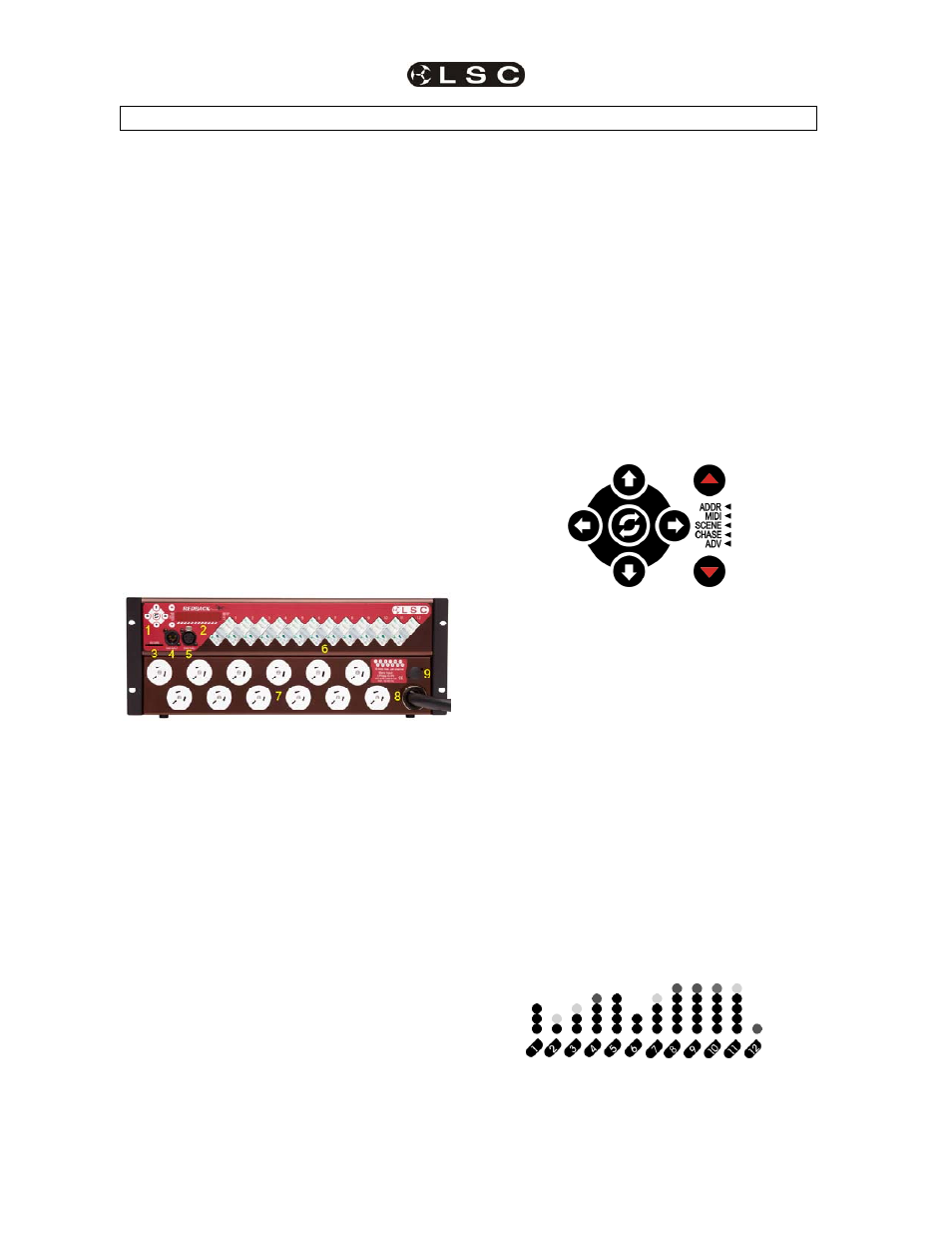
1.1 Redback Layout
Redback is a rack mounting device that
occupies 2RU (89mm) in a standard 19"
(484mm) equipment rack.
The versions with front mounted connectors
occupy 4RU (178mm).
The front panel of all versions:
1 Control
panel
2 LED
display
3
SD Flash memory card slot
4 DMX512
Input
connector
5 DMX512
Through
socket
6
Load circuit breakers
Rear panel of 2RU versions and the front panel
of 4RU versions.
7
Load connectors
8
Power supply entry (multiple entry
points available on 4RU models)
9 MIDI
IN
socket
(optional).
1.2 Power Supply
6 channel Redbacks can be powered from:
Three phase supply of nominal 100-
120 or 220-240VAC at 50 - 60Hz of up
to 20 Amps per phase.
Single phase supply of nominal 100-
120 or 220-240VAC at 50 - 60Hz of up
to 60 Amps
12 channel Redbacks can be powered from:
Three phase supply of nominal 100-
120 or 220-240VAC at 50 - 60Hz of up
to 40 Amps per phase.
Single phase supply of nominal 100-
120 or 220-240VAC at 50 - 60Hz of up
to 60 Amps.
Note: 100-120VAC versions to be specially
ordered and supplied direct from the factory.
Safety Note: Conversion between three phase and
single phase operation should only be undertaken by a
suitably trained and qualified electrical technician.
1.3 Control Panel
All control and configuration operations on
Redback are accessed using the five-button
control pad and the Menu scroll keys.
The
Left and Right arrow keys are used to
step between the parameters being set in the
selected function.
The
Up and Down arrow keys are generally
used to increase or decrease the values for the
selected parameter.
The
3 Flip key is generally used to switch
between text and graphical modes on the LED
display.
The red Menu Up
S
and Menu Down
T
keys
scroll between menu functions.
The menu LEDs
W indicate the currently active
menu function.
1.4 LED Display
The LED panel has both text and graphical
display modes.
D M X 1 3
Menu information is generally displayed as text.
Dimmer levels are displayed in graphical mode.
(12 channel display shown)