Advanced connections, Connecting the remote control jacks, English – Marantz NR1501 User Manual
Page 20: Names and functions, The setting “enable” is shown on the fl display
NAMES AND
FUNCTIONS
16
BASIC
CONNECTIONS
BASIC
OPERA
TION
ADV
ANCED
CONNECTIONS
SETUP
ADV
ANCED
OPERA
TION
TROUBLESHOOTING
OTHERS
ADV
ANCED
CONNECTIONS
ENGLISH
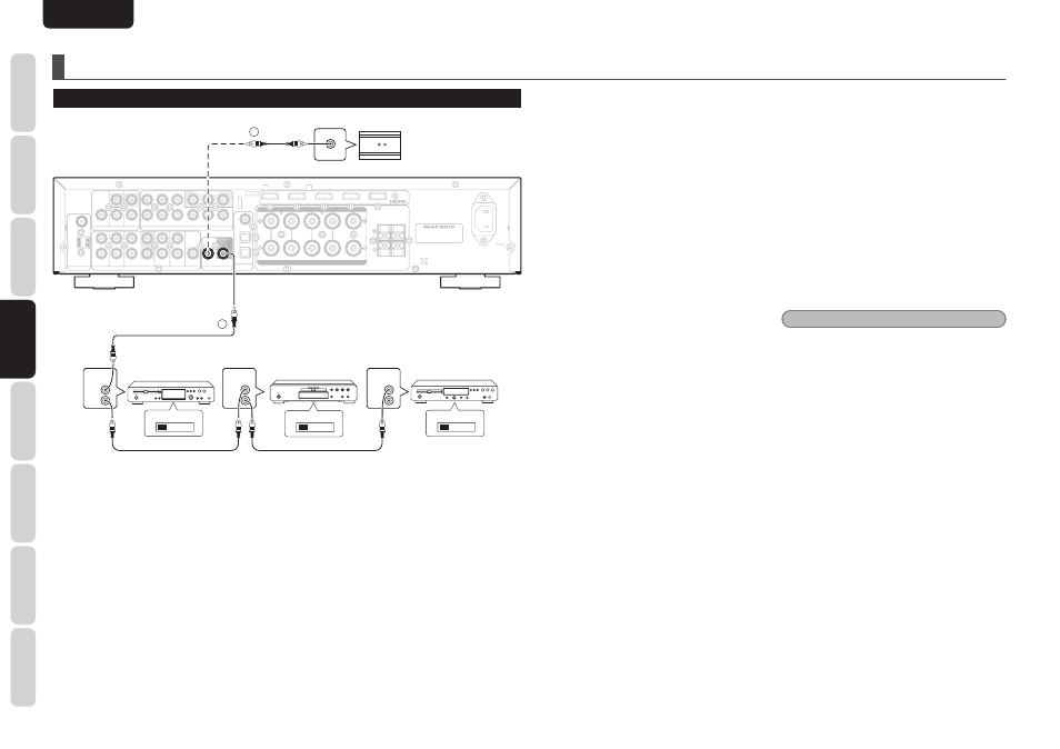
ADVANCED CONNECTIONS
CONNECTING THE REMOTE CONTROL JACKS
IN
IN
OUT
OUT
PRE OUT
PRE OUT
GAME
GAME
DVD
DVD
DSS
DSS
L
L
R
R
DIGITAL
DIGITAL
AUDIO
AUDIO
IN
IN
SURROUND BACK
SURROUND BACK
R
R
L
L
3
3
2
2
1
1
GND
GND
AM
AM
AC IN
AC IN
MODEL NO. NR1501
MODEL NO. NR1501
VIDEO
VIDEO
FM
FM
((75
75
Ω
Ω))
SPEAKER SYSTEMS : 6-8 OHMS
SPEAKER SYSTEMS : 6-8 OHMS
COMPONENT VIDEO
COMPONENT VIDEO
DVD
DVD
MONITOR OUT
MONITOR OUT
OUT
OUT
MONITOR OUT
MONITOR OUT
IN
IN
IN
IN
IN
IN
IN
IN
IN
IN
OUT
OUT
SUB
SUB
DVD
DVD
DSS
DSS
VCR
VCR
CD
CD
AUX 2
AUX 2
WOOFER
WOOFER
ANTENNA
ANTENNA
REMOTE CONTROL
REMOTE CONTROL
ANALOG AUDIO
ANALOG AUDIO
DSS
DSS
VCR
VCR
IN
IN
IN
IN
DVD
DVD
DSS
DSS
IN
IN
VCR
VCR
P
P
R
R
//C
C
R
R
P
P
R
R
//C
C
R
R
P
P
B
B
//C
C
B
B
P
P
B
B
//C
C
B
B
Y
Y
Y
Y
OUT
OUT
BLU-RAY
BLU-RAY
CENTER
CENTER
R
R -
- SURR.
SURR. -
- L
L
R
R -
- FRONT
FRONT -
- L
L
IN
IN
OUT
OUT
REMOTE CONTROL
REMOTE CONTROL
REMOTE
CONTROL
REMOTE
CONTROL
REMOTE
CONTROL
IN
OUT
IN
OUT
IN
OUT
EXTERNAL INTERNAL
EXTERNAL INTERNAL
EXTERNAL INTERNAL
1
RC OUT
2
Option
DVD player
CD player
CD recorder
q
You can control other Marantz products through this
unit with the remote controller by connecting the
REMOTE CONTROL terminals on each unit.
The signal transmitted from the remote controller
is received by the remote sensor on this unit. Then
the signal is sent to the connected device through
this terminal. Therefore you need to aim the remote
control only at the unit. Also, if a Marantz power
amplifier (some models excluded) is connected
to one of these terminals, the power amplifi er’s,
power switch is synchronized with this unit’s power
switch.
Set the REMOTE CONTROL SWITCH on the back of
other units (not the NR1501) to “EXT.” (EXTERNAL)
to use this feature.
w
Whenever external infrared sensors or similar
devices are connected to RC-5 IN of the unit, be sure
to always disable operation of the infrared sensor on
the unit by using the following procedure.
1.
Hold down the
3 cursor button and the
MENU button on the front panel at the
same time for fi ve seconds.
2.
The setting “ENABLE” is shown on the FL
DISPLAY.
3.
Press
the
CURSOR buttons (
1, 2) to change
this to “DISABLE”.
4.
Press
the
ENTER button. Once this setting
is made, the infrared sensor on the unit is
disabled.
Note
• Be sure to set to “ENABLE” when external
infrared sensors or similar devices are not
connected. Otherwise, the unit will be unable to
receive remote control commands.
5.
To restore the original setting, perform
steps 1 to 4 to set to “ENABLE”.