Names and functions, Fl diplay and indicator – Marantz NR1501 User Manual
Page 8
NAMES AND
FUNCTIONS
4
BASIC
CONNECTIONS
BASIC
OPERA
TION
ADV
ANCED
CONNECTIONS
SETUP
ADV
ANCED
OPERA
TION
TROUBLESHOOTING
OTHERS
NAMES AND
FUNCTIONS
ENGLISH
NAMES AND FUNCTIONS
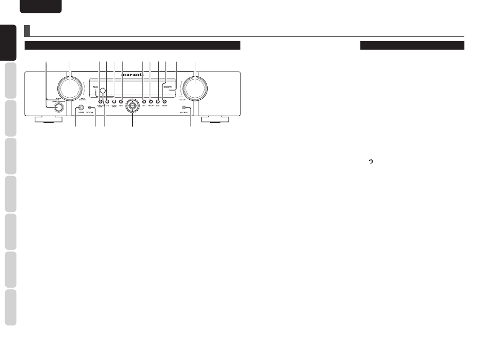
FRONT PANEL
q
w
!2
ert y
ui o!0 !1
!4
!3
!6
!7
!5
q POWER switch and STANDBY
indicator
When this switch is pressed once, the unit turns ON
and the display illuminates. When pressed again,
the unit turns OFF and the STANDBY indicator will
be illuminated.
w INPUT SELECTOR knob
This knob is used to select the input sources. (See
page 13)
e SURROUND MODE button
Press this button to select the surround mode.
r AUTO button
Press this button to select the AUTO mode from the
surround modes. When this mode is selected, the
unit determines the surround mode corresponding
to a digital input signal automatically. (See page 27)
t SOURCE DIRECT button and
indicactor
When this button is pressed, the audio signal will
bypass the tone control circuit to provide the pure
sound quality.
In order not to bypass the tone control circuit, press
SOURCE DIRECT button again.
y MENU button
Press this button to enter the SETUP MAIN
MENU.
u EXIT button
Press this button to exit from the SETUP MAIN
MENU.
i DISPLAY button
Press this button to change the FL display mode.
(See page 26)
o BAND button
Press this button to switch between FM and AM in
the TUNER mode.
!0 MEMORY button
Press this button to enter the tuner preset memory
numbers or station names. (See page 30)
!1 HDMI indicator
This indicator is illuminated when input terminal of
the HDMI component is connected to the unit.
!2 VOLUME control knob
This knob is used to adjust the overall sound level.
Turning the control clockwise increases the sound
level.
!3 AUX1 INPUT jack
This audio input jack accept the connections of the
portable audio player etc.
!4 Cursor (
3, 4, 1, 2) / ENTER button
Press these buttons to operate the SETUP MAIN
MENU and TUNER function.
!5 INFRARED receiving sensor
window
This window receives infrared signals for the
remote controller.
!6 SETUP MIC jack
Automatically measure speaker characteristics
using the included microphone. (See page 22)
!7 PHONES jack
This jack may be used to listen to the unit’s output
through a pair of headphones. (See page 28)
FL DIPLAY AND INDICATOR
a Main Information Display
This display shows messages relating to the status,
input source, surround mode, tuner, volume level or
other aspects of unit’s operation.
s AUTO indicator
This indicator is illuminated when the AUTO
SURROUND mode is in use.
d TUNER’s indicators
ST : This indicator is illuminated in the AUTO
STEREO mode during tuner operations.
TUNED : This indicator illuminates when the tuner
receives a suffi ciently strong radio signal.
f indicator
This indicator is illuminated when the sleep timer
function is in use.
g MEM indicator
This indicator is illuminated when the MEMORY
function is working during tuner operations.
h PRESET indicator
This indicator is illuminated in the PRESET mode
during tuner operations.
j HDMI indicator
This indicator is illuminated when a HDMI input
source has been selected.