Measurement Computing eZ-Analyst rev.14.1 User Manual
Page 24
3-6 Menus
878193
eZ-Analyst
When you are in “Measurement Mode” you can access the Calibration window from the Task
Menu or from the Input/Output Channels tab.
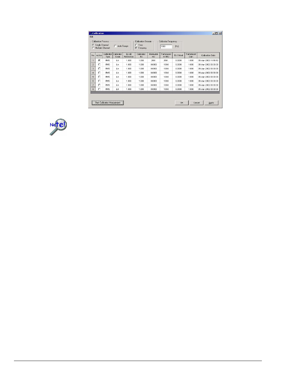
Calibration Display Screen
When a channel is calibrated, the number of averages used will be 5, or the
number that is designated in the “No. of Averages” field (located on the
Analyzer Tab). The greater of the two values will be used, automatically.
A discussion of the various regions of the Calibration window now follows.
The section concludes with an example.
Calibration Process
Single
Channel
Used to select one active channel at a time. When the calibrator only has
one channel output, the Single Channel method must be used. When
Single Channel is selected, the “Active” column shows a radio button next
to each channel.
Multiple
Channel
Used to select two or more channels for simultaneous calibration. This is
only an option when the calibrator offers more than one output. When
Multiple Channel is selected, the “Active” column shows a checkbox next to
each channel.
Calibration Domain
With the use of Fourier Transform, any signal can be viewed from a time domain or a
frequency domain. Either domain can be selected for use in the calibration process.
Time
The overall value is computed using time domain data.
Freq-
uency
The overall value is computed with frequency domain data by summing up
frequency component of FFT spectrum.
Calibrator Frequency (Hz)
This field is used to enter the frequency setting of the calibrator. The analysis frequency,
which is twice this frequency, is used if possible. Otherwise, the maximum allowed
analysis frequency is used.