Microcom 814M Programming Manual User Manual
Page 50
46
• If the settings are changed, they become effective when the BA-T500 is reset other power is turned
on again.
• The setting values can be checked by executing the self-test.
GS ( E pL pH m a (m = 4) <Function 4>
[Format]
ASCII
GS
(
E p
L
p
H
m
a
Hex
1D
28
45
p
L
p
H
04 a
Decimal 29
40
69 p
L
p
H
4 a
[Range]
( p
L
+ p
H
x 256) = 2 ( p
L
= 2
,
p
H
= 0)
m = 4
1
≤
a
≤
8
[Function]
Sends the setting values of the memory switch specified with a
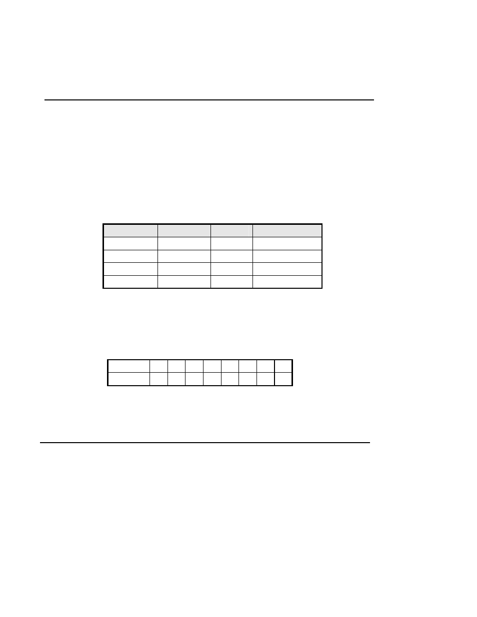
The contents of the transmit data are as follows:
Transmit data Hex
Decimal
Number of data
①
Header
37H 55
1
byte
②
Flag
21H 33
1
byte
③
Data
30H, 31H
48, 49
8 bytes
④
NUL
00H 0 1
byte
Contents of data shown in ③ above:
The on/off setting of the memory switch is defined as [Off: Hex=30H/Decimal=48] or [On: Hex=31H
/ Decimal=49]. Each 1 byte for 8 memory switches are transmitted from bit 8 to bit 1.
Example: Transmitted data: “10110001”
(31H, 30H, 31H, 31H, 30H, 30H, 30H, 31H)
Switch
No.
8 7 6 5 4 3 2 1
Status
On
Off On On Off Off Off On
• If an unsupported memory switch number is selected, this command is ignored.
• If this command is ignored, the printer doesn’t send any data.
GS * x y d1...d(x × y × 8)
[Name]
[Format]
[Range]
[Description]
Define downloaded bit image
ASCII
GS
*
x y d1...d(x × y × 8)
Hex
1D
2A
x y d1...d(x × y × 8)
Decimal 29
42
x y d1...d(x × y × 8)
1 ≤ x ≤ 255, 1 ≤ y ≤ 255
x × y ≤ 2048
0 ≤ d ≤ 255
Defines a downloaded bit image using the number of bytes specified by x and y
♦ x specifies the number of dots in the horizontal direction.