D event input configuration, Devent input configuration – NavCom SF-2050 Rev.D User Manual
Page 51
SF-2050 User Guide - Rev. D
D
Event Input Configuration
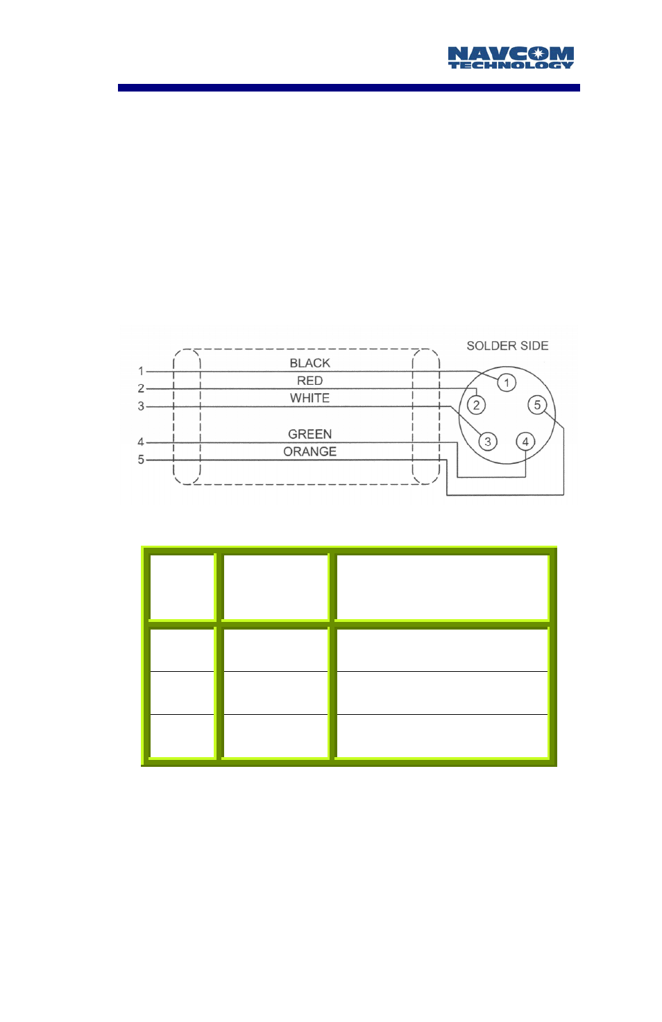
Figure D1 details the wiring of the Event/Can cable
assembly NavCom part number P/N 94-310062-3003.
The Event Input is electrically isolated to the internal
circuitry through an opto-isolator, thus a voltage of 3-6
vdc/50Ω (60 - 120mA), and a minimum pulse width of
100nSec must be sensed in order to get through the
opto-isolator. Table D1 details the wiring configuration
required for Event-Hi, and Event-Lo pulse sensing.
Figure D1: Event Cable Wiring Diagram
Pin #
Signal
Name
Event Sync Wiring
1
Event Lo
Tie Event-Hi to Ground
2
Event Hi
Tie Event-Lo to Ground
3 Ground
N/A
Table D1: Event Wiring Connections
Once the cable is wired to correspond with the event
pulse requirements, the receiver must be configured to
output the message containing a time mark indicating
when the event is sensed. The time will be referenced
to the time kept within the NavCom receiver.
D-49