2 electrical installation condair me direct feed, Electrical installation nortec me direct feed, 2 electrical installation nortec me direct feed – Nortec ME Direct Feed Installation User Manual
Page 35: 35 installation
35
Installation
4.6.2 Electrical installation Nortec ME Direct Feed
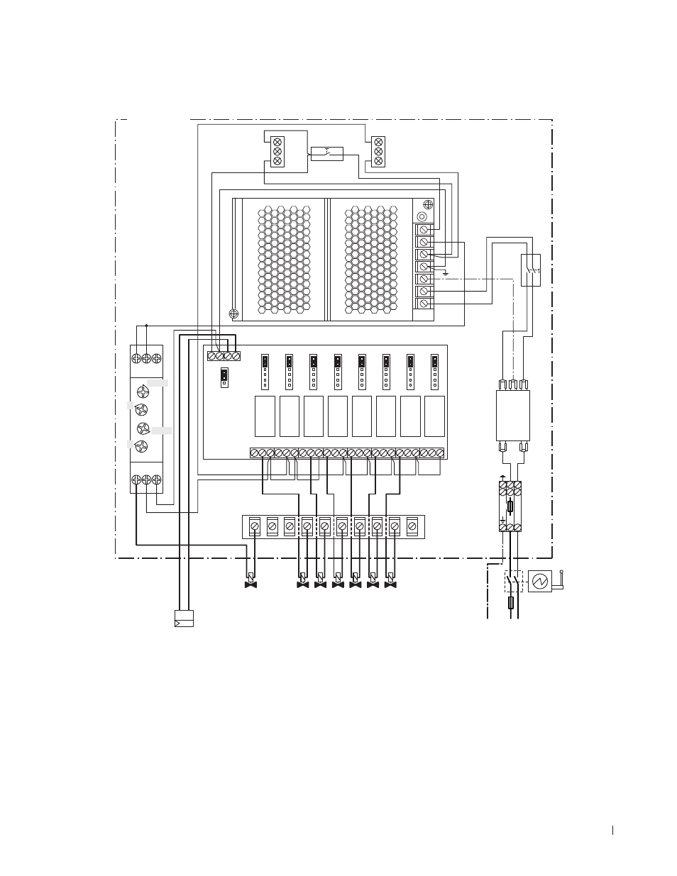
4.6.2.1 Wiring diagram Nortec ME Direct Feed with stage control
LED 2
LED 1
S1
T1
A1
R1
JP1
XS
XR
XE1
RELAY1 RELAY2 RELAY3 RELAY4 RELAY5 RELAY6 RELAY7 RELAY8
PE
L
N
F1
Q
B1
PMC-24V100W1AA
NC NO C
NC NO C
NC NO C NC NO C
NC NO C NC NO C
NC NO C
NC NO C
STG
SEQ
OFF
OFF
ON
STG
SEQ
OFF
OFF
ON
STG
SEQ
OFF
OFF
ON
STG
SEQ
OFF
OFF
ON
STG
SEQ
OFF
OFF
ON
STG
SEQ
OFF
OFF
ON
STG
SEQ
OFF
OFF
ON
STG
SEQ
OFF
OFF
ON
0-10
24V 0V 0V IP
2-10
–
+
100...240 V/1~/50..60 Hz
P/PI
N
L
PE N
L
NF
L N
F2
S2
A1 15 Y1
18 16 A2
Toff
Ton
1-10min
10-100h
2
3
A1
I/O board
B1
Demand signal 0...10V or 2...10V
F1
External fuse mains supply (10 A, slow acting)
F2
Internal fuse mains supply (6.3 A, fast acting)
JP1
Jumper control signal (Jumper fitted on 0..10V)
LED 1
LED white (control unit switched ON)
LED 2
LED green (humidification ON)
NF
Mains filter
Q
Electrical isolator
R1
Timer purge valve
S1
Humidification On/Off switch
S2
On/Off switch control unit
T1
24V power supply
XE1
Terminal mains supply voltage
XR
Terminals 24V valves
XS
Ground terminals valves
Fig. 21: Wiring diagram Nortec ME Direct Feed with optional stage control unit
Outlet
Purge valve
Inlet
Stage 2
Stage 3
Stage 4
Stage 5
Control unit