36 installation – Nortec ME Direct Feed Installation User Manual
Page 36
36 Installation
4.6.3
Installation work Nortec ME Direct Feed with stage control
Note: for the connection of the available options please refer to the installation and operation manual of
the corresponding option. The safety monitoring of the operation of the humidification/cooling system
via a safety chain (max. humidity monitor, air flow monitor, etc.) is the responsibility of the client.
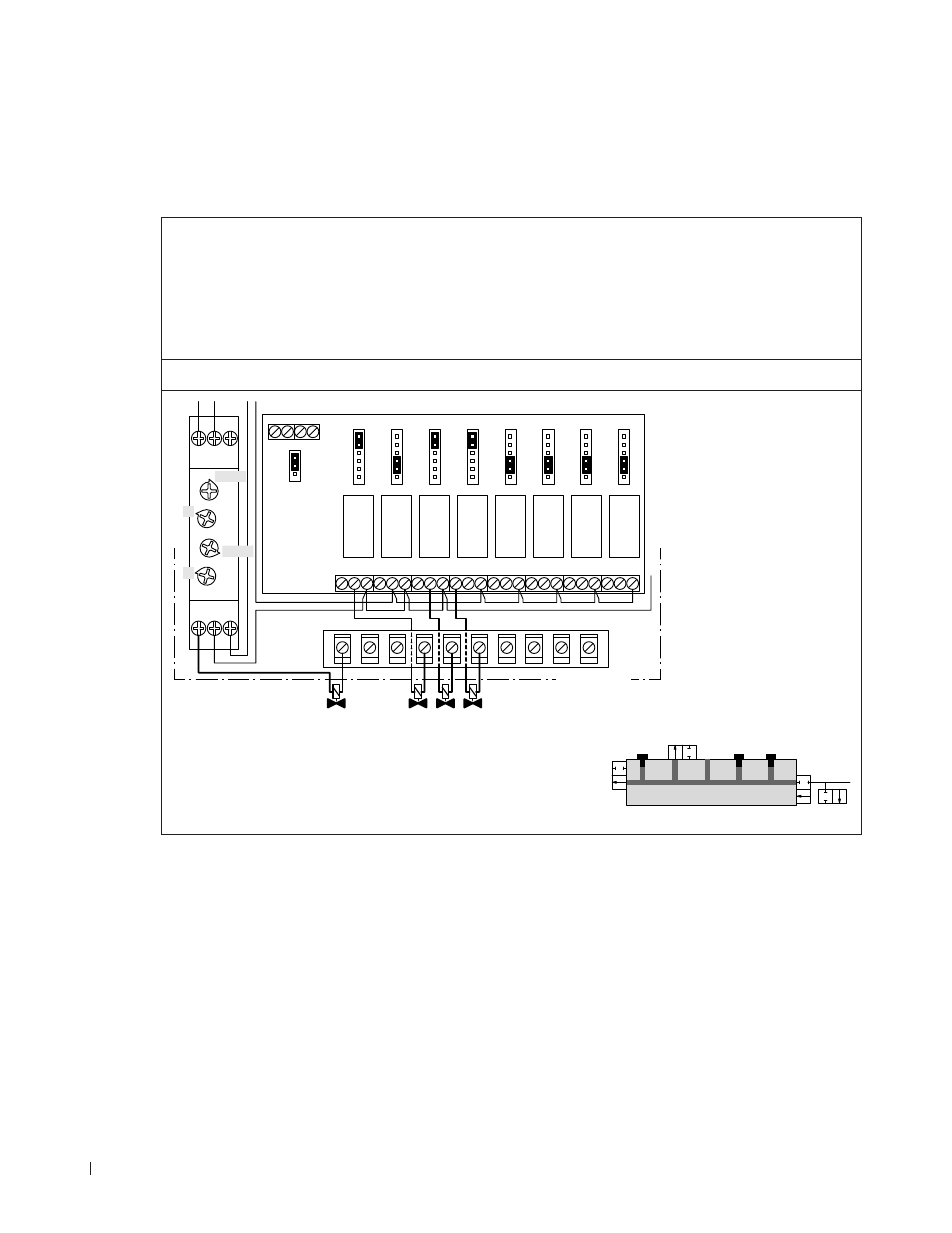
Connecting the valves of the Hydraulic manifold
Note: Relay 1 to 8 on the IO board are switched dependent on the percentage of the demand signal.
For this reason the valves must be connected to the control unit according to the corresponding stage
control diagram and the relays on the IO board must be configured accordingly via the corresponding
jumpers.
The connecting cable must be fed through the rectangular cable feed through into the control unit.
–
Wiring and Jumper settings 2 stage control with purge valve
Outlet
Inlet
Purge
Stage 1
Stage 2
Outlet (17 %)
Purge valve
Inlet (39 %)
Stage 2 (72 %)
A1
JP1
XR
RELAY1 RELAY2 RELAY3 RELAY4 RELAY5 RELAY6 RELAY7 RELAY8
NC NO C
NC NO C
NC NO C NC NO C
NC NO C NC NO C
NC NO C
NC NO C
STG
SEQ
OFF
OFF
ON
STG
SEQ
OFF
OFF
ON
STG
SEQ
OFF
OFF
ON
STG
SEQ
OFF
OFF
ON
STG
SEQ
OFF
OFF
ON
STG
SEQ
OFF
OFF
ON
STG
SEQ
OFF
OFF
ON
STG
SEQ
OFF
OFF
ON
0-10
24V 0V 0V IP
2-10
R1
XS
A1 15 Y1
18 16 A2
Toff
Ton
1-10min
10-100h
2
3
Control unit