38 installation, Control signal – Nortec ME Direct Feed Installation User Manual
Page 38
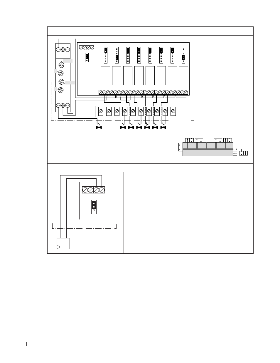
38 Installation
–
Wiring and Jumper settings 5 stage control with purge valve
Outlet
Inlet
Purge
Stage 1
Stage 3
Stage 5
Stage 4
Stage 2
Outlet (17 %)
Purge valve
Inlet (39 %)
Stage 3 (61 %)
Stage 4 (72 %)
Stage 5 (83 %)
Stage 2 (50 %)
A1
JP1
XR
RELAY1 RELAY2 RELAY3 RELAY4 RELAY5 RELAY6 RELAY7 RELAY8
NC NO C
NC NO C
NC NO C NC NO C
NC NO C NC NO C
NC NO C
NC NO C
STG
SEQ
OFF
OFF
ON
STG
SEQ
OFF
OFF
ON
STG
SEQ
OFF
OFF
ON
STG
SEQ
OFF
OFF
ON
STG
SEQ
OFF
OFF
ON
STG
SEQ
OFF
OFF
ON
STG
SEQ
OFF
OFF
ON
STG
SEQ
OFF
OFF
ON
0-10
24V 0V 0V IP
2-10
R1
XS
A1 15 Y1
18 16 A2
Toff
Ton
1-10min
10-100h
2
3
Control unit
Control Signal
JP1
B1
0-10
24V 0V 0V IP
2-10
–
+
P/PI
Control unit
Connect an
external controller to the corresponding terminals
(0V= "–”, IP= “+”) on the IO board. The connecting cable must
be fed through the rectangular cable feed through into the
control unit.
Admissible control signals are 0-10VDC or 2-10VDC selctable
via the Jumper JP1 on the IO board.