Ò³ãæ 55, Wiring and final preparation – Onwa Marine Electronics KR-1338C v.1 User Manual
Page 55
Wiring and final preparation
4.
5.
6.
9.
7.
8.
Drill a hole of at least 20 millimeters diameter through the deck or bulkhead
to run the signal cable between the antenna unit and display unit. (To
prevent electrical interference avoid running the signal cable near other
electrical equipment and in parallel with power cables.) Pass the cable through
the hole. Then, seal the hole with sealing compound for waterproofing
Remove the shield cover in the radome.
Remove the cable clamping plate by unfastening four screws and removing
a gasket.
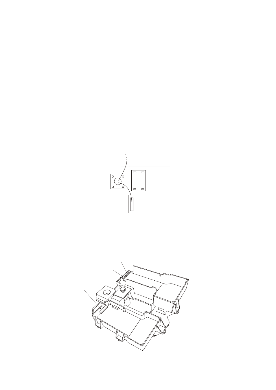
Connect the wire to the RF unit.
(1) 9-pin connector to J801
2
(3) 13-pin connector to J611
( ) 4-pin connector to J802
Pass the cable through the hole at the bottom of the radome base.
Secure the cable with the cable clamping plate and gasket. Ground the shield
and vinyl wire by one of the screws of the cable clamping plate and one of
the screws of the IF amplifier chassis, respectively.
Motor
If0711
J801
J802
J611
Figure 6-4 Location of J801/J802/J611
47