Pulse width trigger – OWON SDS Series User Manual
Page 42
5.Advanced User Guidebook
Set slope condition; turn the M knob to set slope
time.
Threshold
&SlewRate
High level
Low level
Slew rate
Adjust M knob to set the
High level
upper limit.
Adjust M knob to set
Low level lower limit.
Slew rate = (
High level - Low level) / Settings
Mode
Holdoff
Auto
Normal
Single
Holdoff
Reset
Acquire waveform even no trigger occurred
Acquire waveform when trigger occurred
When trigger occurs, acquire one waveform then stop
100ns ~ 10s, turn the M knob to set time interval
before another trigger occur.
Set Holdoff time as 100ns
4. Pulse Width Trigger
Pulse trigger occurs according to the width of pulse. The abnormal signals can be
detected through setting up the pulse width condition.
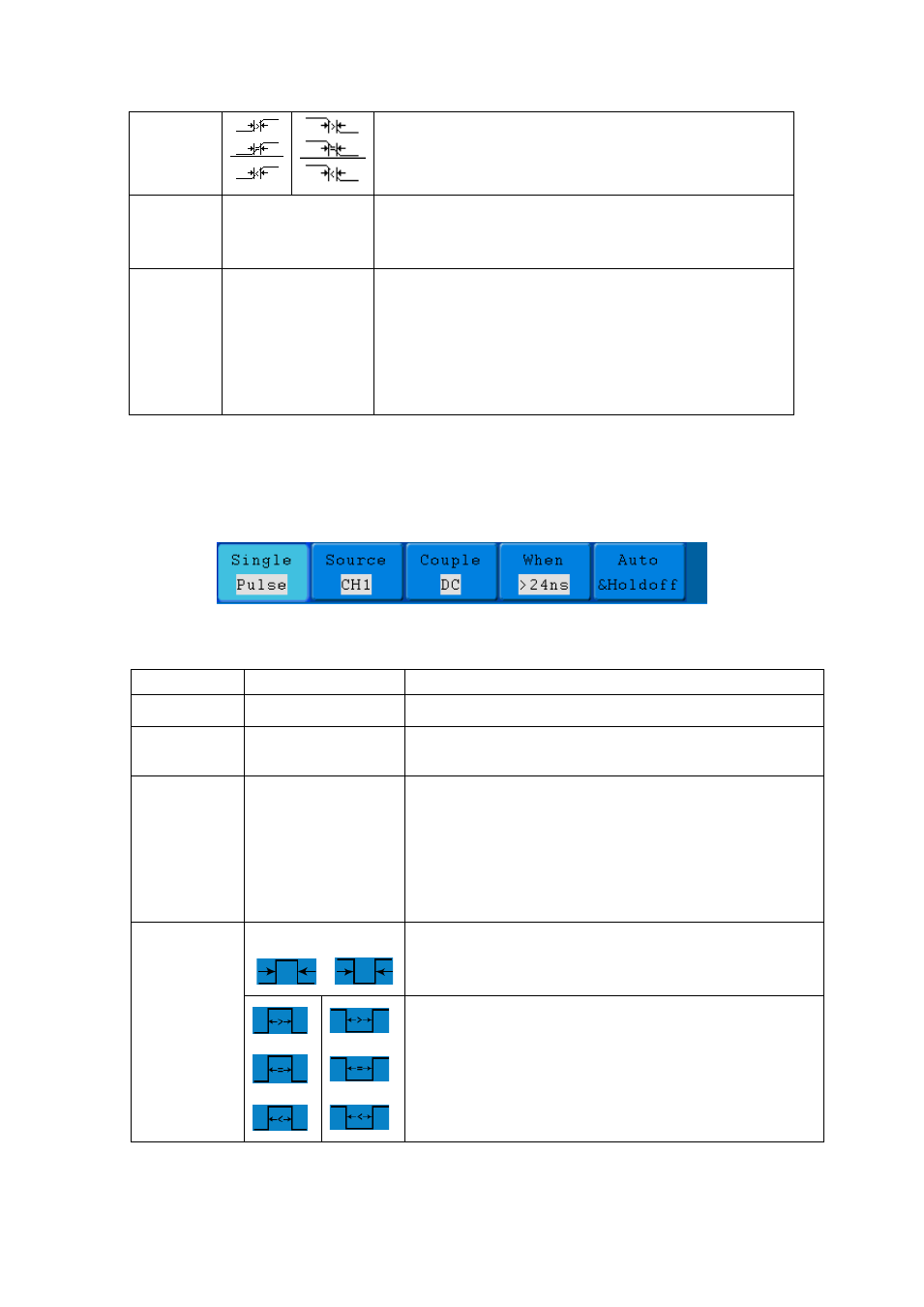
The Pulse Width Trigger Menu is shown as Figure 5-19.
Figure 5-19 Pulse Width Trigger menu
Pulse Width Trigger menu list:
MENU
SETTING
INSTRUCTION
Single Mode
Pulse
Set vertical channel trigger type as pulse trigger.
Source
CH1
CH2
Select CH1 as the trigger source.
Select CH2 as the trigger source.
Coupling
AC
DC
HF
LF
Not allow DC portion to pass.
Allow all portion pass.
Not allow high frequency of signal pass and only low
frequency portion pass.
Not allow low frequency of signal pass and only high
frequency portion pass
when
Polarity
Choose the polarity
Select pulse width condition and adjust the M knob
to set time.
37