Chapter 6: appendices – Smart Avi SmartNet-V User Manual
Page 23
Page 23
MNSNV102005Ver1.0
Chapter 6: Appendices
Chapter 6: Appendices
Chapter 6: Appendices
Chapter 6: Appendices
Chapter 6: Appendices
1.0 D
1.0 D
1.0 D
1.0 D
1.0 Dooooocum
cum
cum
cum
cumeeeeent
nt
nt
nt
nt C
CC
C
Conventions
onventions
onventions
onventions
onventions
Any numbers preceded by ‘0x’ are hexadecimal.
(base 16) All data byte string listed in
examples are in hexadecimal.
(base 16)
2.0 Comms Ports Settings.
2.0 Comms Ports Settings.
2.0 Comms Ports Settings.
2.0 Comms Ports Settings.
2.0 Comms Ports Settings.
The Host Controller Serial Port should be configured as detailed in the table below
3.0 RS232/422 converter.
3.0 RS232/422 converter.
3.0 RS232/422 converter.
3.0 RS232/422 converter.
3.0 RS232/422 converter.
The Frame control interface uses RS422. A full duplex 5 wire balanced communications
standard that allows communications to be multi-dropped to more than one Frame.
Since PC’s only come with RS232 ports a small converter is required to convert the RS232
signals to RS422.
If you purchased any of the SmartControl software options you will have received a suitable
converter and cable.
In the event that you wish to purchase your own converter and/or make your own comms cable
please see Appendix A at the rear of this document for more information.
4.0
4.0
4.0
4.0
4.0 Conne
Conne
Conne
Conne
Connecti
cti
cti
cti
cting
ng
ng
ng
ng up
up
up
up
up
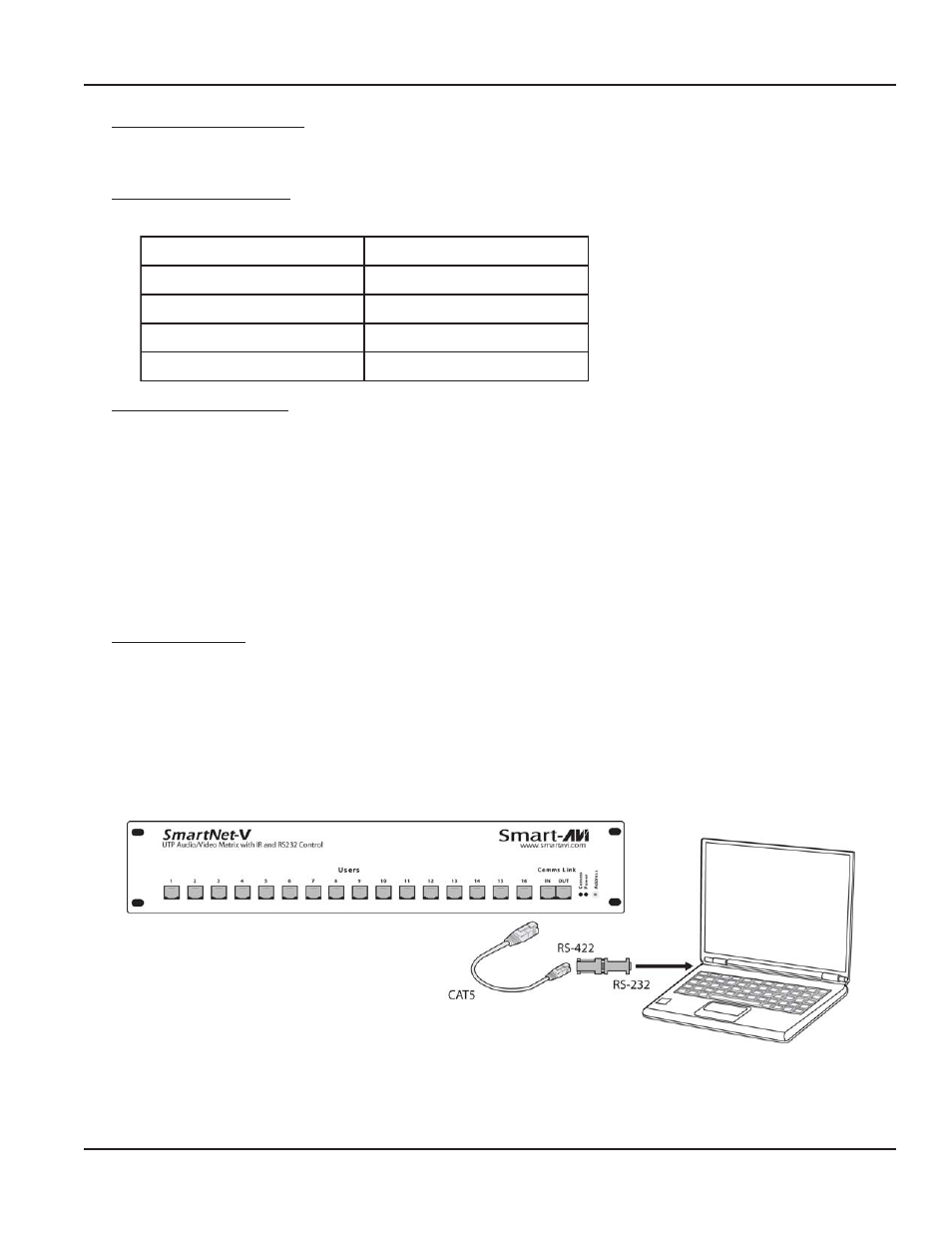
4.1. Plug the RS232 end of the RS232 to RS422 converter directly onto the selected comms port
on the rear of your computer.
4.2. Plug the comms cable (D9 end) onto the end of the RS422 end of the RS232/RS422
converter.
4.3. Plug the RJ45 end of the comms cable into the IN port on the front of the SmartNet-X or
SmartNet-V.
e
t
a
R
d
u
a
B
0
0
6
9
s
t
i
B
t
r
a
t
S
1
s
t
i
B
a
t
a
D
8
y
t
i
r
a
P
e
n
o
N
s
t
i
B
p
o
t
S
1