Chapter 2: installation – Smart Avi SmartNet-V User Manual
Page 9
Page 9
MNSNV102005Ver1.0
Chapter 2: Installation
Chapter 2: Installation
Chapter 2: Installation
Chapter 2: Installation
Chapter 2: Installation
Connecting the Communication Cable: RS422
Connecting the Communication Cable: RS422
Connecting the Communication Cable: RS422
Connecting the Communication Cable: RS422
Connecting the Communication Cable: RS422
Each unit can be controlled by a RS422 port connected via a RJ45 on the front of the chassis. Two
connectors are provided for expansion, allowing a simple Cat 5 patch cable to link to additional units.
An adjustable rotary switch allows each unit to be assigned a unique ID, read when the unit is first
powered up. The SmartControl software will be used to control the units.
Note: In addition to the centralized control from a computer, each output can be selected individually.
The receiver unit either has an internal IR decoder or and optional external IR decoder. Using a handset
or other third party system each output can be selected by simply pressing the appropriate number
corresponding to the input number.
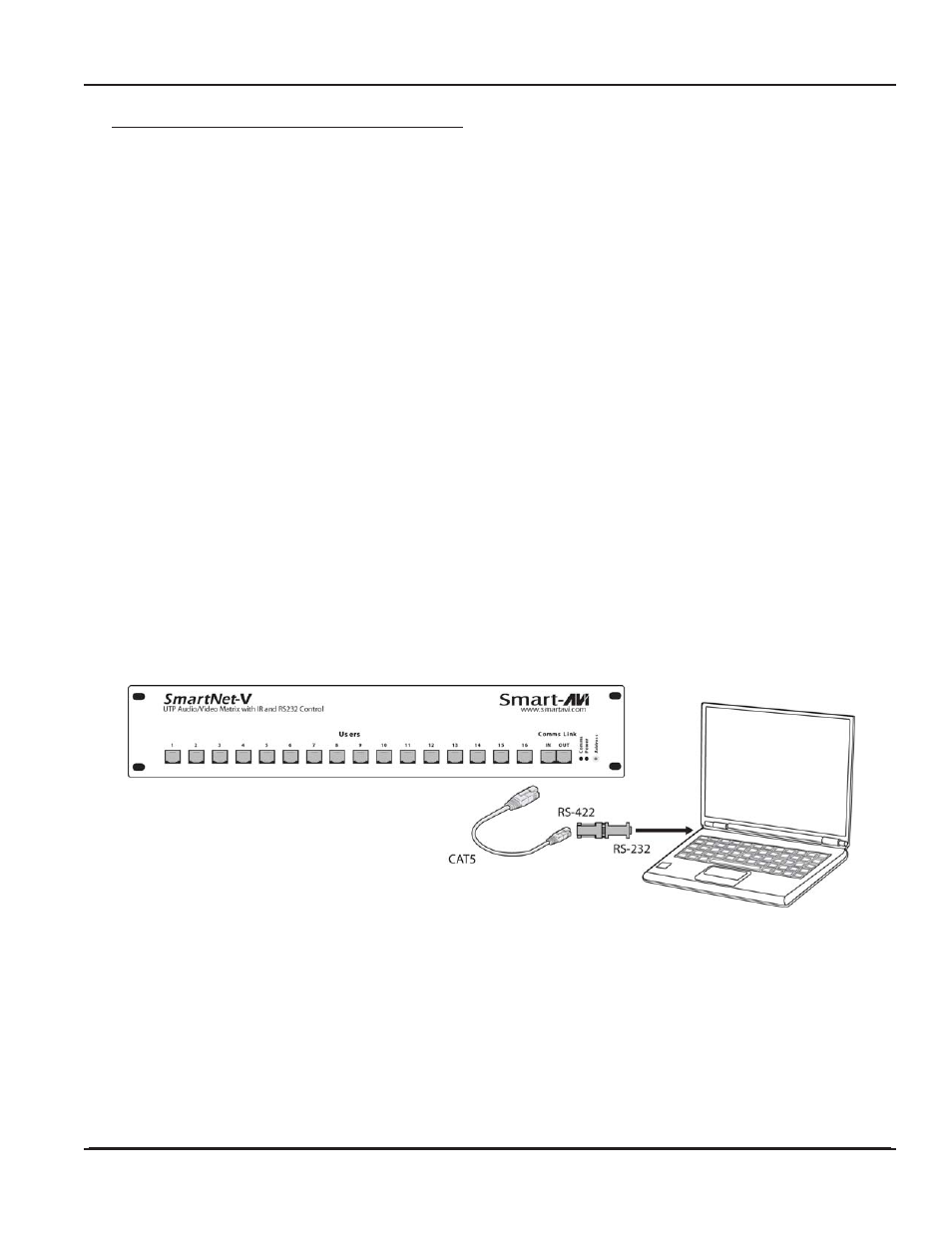
There are 2 adapters:
•
RS232 to RS422 adapter (Connects to the serial port on your computer)
•
RS422 to RJ45 adapter (Connects to the other adapter as well as SmartNet-X Unit)
1.
Connect the RS232 to RS422 adapter into the control computer by connecting the female
RS232 connector into the male RS232 connector of the PC. Turn the side screws so that it
does not accidentally become disconnected
2.
Connect the RS422 to RJ45 adapter to the other adapter by connecting the female end into
the male connector of the other adapter.
3.
Run a single UTP CAT5 cable from this connector to the front of the SmartNet-V unit.
4.
Connect CAT5 connector to the COMMS connector labeled IN.